Product Description
Company Profile
HangZhou CZPT Manufacture Co., Ltd is located in Xihu (West Lake) Dis. District, HangZhou City, has a wealth experience of forging, machining, producing and markting. We competitively engages in all kinds shape of steel heads for pressure vessel and kinds of auto heavy truck parts, and been the long cooperative supplier for HOWO, Styer, Hyundai, JAC, Xihu (West Lake) Dis.feng, FAW, etc.
Product Details
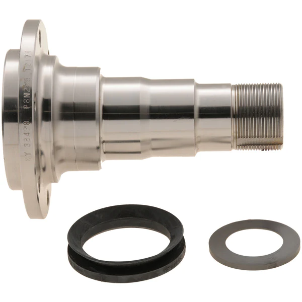
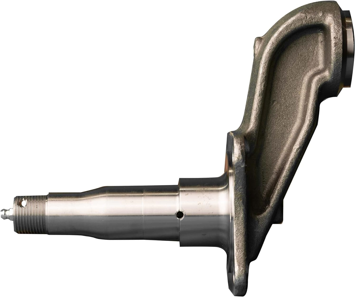
| Name | High quality Gearbox spindle for auto parts |
| Material | 40Cr or customized |
| Specifications | According to customer drawing |
| Surface | Rust proofing |
| Tolerance | According to the customer request |
| Customized | We accept customized product. |
| Technology | Advanced heat treatment stronger resistance to pressure |
| Application | Applied to the truck chassis system |
| Quality standard | ISO 9001:2008 Quality system certification |
Product Picture
Product Features
· Accurate size
· High tensile strength
· Attractive appearance
· High cost performance
· Long service life
· ISO9001:2008 certificate
What We Have
· China Leading Producing Technology
· Good Quality
· Competitive Price
· Big Production Ability
· Fast Delivery
· 15 Years’ Production Experience
· Excellent Sale and After-sale Service
FAQ
1. Are you a factory or a trading company?
We are a factory and established in 2003.
2. Is OEM available?
Yes, OEM is available.
3. Is the sample available?
Yes, samples are available for you to test the quality.
4. Are the products tested before shipping?
Yes, all of our products were inspected piece by piece and they are all qualified before shipping.
5. What’s your quality guarantee?
ISO 9001:2008 Quality system authentication
6. What’s benefit will you bring?
· Your clients will be satisfied wih the quality.
· Your clients will continue orders.
· You can get good reputation from your market and obtain more orders.
7. How about the payment terms?
A: TT, L/C, Paypal and etc
8. How to Packing?
We usually use the iron box, Tito’s plate or wooden case,also can be customized according to customer’s packaging requirements
For more information, pls don’t hesitate to contact us & we are prepared to be challenged, looking forward to get involved in your next project!
/* January 22, 2571 19:08:37 */!function(){function s(e,r){var a,o={};try{e&&e.split(“,”).forEach(function(e,t){e&&(a=e.match(/(.*?):(.*)$/))&&1
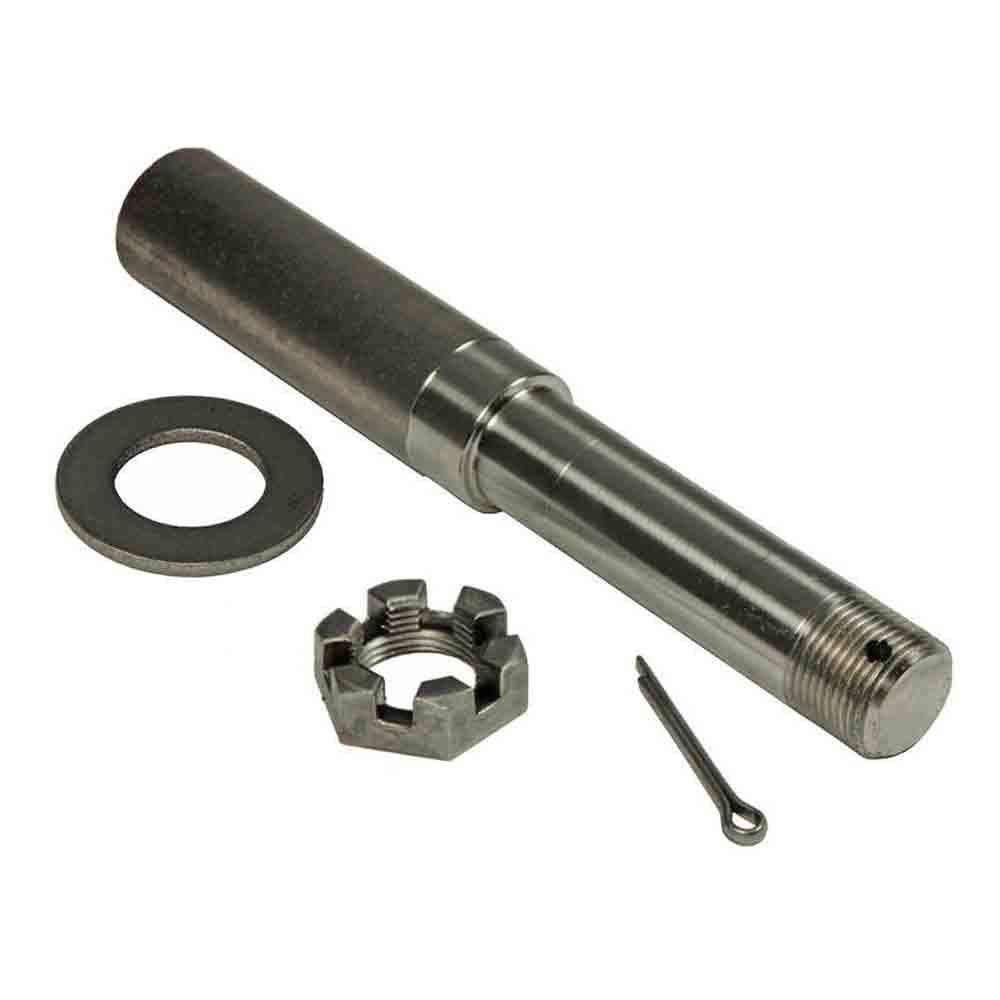
| Type: | Truck Parts |
|---|---|
| Application: | Both Ends of The Rear Axle |
| Certification: | ISO9001: 2000 |
| Condition: | New |
| Material: | 40cr |
| Surface: | Rust Proofing |
| Samples: |
US$ 10/Piece
1 Piece(Min.Order) | |
|---|
| Customization: |
Available
| Customized Request |
|---|
What is the relationship between the axle spindle and the wheel bearing in a vehicle?
In a vehicle, the axle spindle and the wheel bearing are two interconnected components that work together to allow the wheel to rotate smoothly and support the vehicle’s weight. Here’s a detailed explanation of their relationship:
The axle spindle is a key part of the vehicle’s suspension system, specifically in the axle assembly. It is a shaft-like component that protrudes from the axle housing and provides support for the wheel assembly. The spindle is typically located at the center of the wheel hub and serves as a mounting point for various components, including the wheel bearing.
The wheel bearing, on the other hand, is a set of precision-engineered bearings that are usually housed within a hub assembly. It is responsible for reducing friction and facilitating the smooth rotation of the wheel. The wheel bearing allows the wheel to spin freely while supporting the weight of the vehicle and enduring the forces generated during acceleration, braking, and cornering.
The relationship between the axle spindle and the wheel bearing is one of integration and mutual dependency. The axle spindle provides the structural support and attachment point for the wheel bearing assembly. The wheel bearing, in turn, enables the wheel to rotate with minimal friction and provides load-bearing capability.
When the vehicle is in motion, the axle spindle transfers the weight of the vehicle and the forces generated by the road surface to the wheel bearing. The wheel bearing, with its lubricated bearings and races, allows the wheel to rotate smoothly and evenly distribute the applied forces. This relationship ensures that the wheel assembly operates effectively, providing stability, control, and a comfortable ride.
Over time, the wheel bearing may experience wear and tear due to continuous use, exposure to contaminants, or lack of proper maintenance. When a wheel bearing becomes worn or damaged, it can lead to various symptoms such as excessive noise, vibration, uneven tire wear, or even wheel detachment. In such cases, it is necessary to replace the wheel bearing assembly, which often involves disassembling the axle spindle to access and replace the bearing.
It’s important to note that the specific design and configuration of the axle spindle and wheel bearing can vary between different vehicle models and manufacturers. Some vehicles may have integrated wheel bearing and hub assemblies, while others may have separate components that are assembled onto the spindle. It is recommended to consult the vehicle’s repair manual or seek professional assistance for specific instructions and procedures related to your vehicle.
In summary, the axle spindle and the wheel bearing have a close relationship in a vehicle’s suspension system. The axle spindle provides structural support and serves as the mounting point for the wheel bearing assembly. The wheel bearing, in turn, allows the wheel to rotate smoothly, supports the vehicle’s weight, and helps absorb the forces generated during driving. Understanding this relationship is important for proper maintenance, repair, and replacement of the wheel bearing assembly.
What is the role of grease and lubrication in maintaining a healthy axle spindle?
Grease and lubrication play a crucial role in maintaining a healthy axle spindle. The axle spindle is a vital component of a vehicle’s suspension system, and proper lubrication is essential to ensure its longevity and performance. Here’s why grease and lubrication are important:
- 1. Friction Reduction: One of the primary functions of grease and lubrication is to reduce friction between moving parts. In the axle spindle, there are multiple points of contact where components rotate or slide. Applying grease minimizes friction and heat generation, which can lead to wear and damage if left unchecked.
- 2. Wear Prevention: Grease forms a protective barrier between metal surfaces, preventing direct metal-to-metal contact. This helps prevent wear and damage to the axle spindle and associated components, such as wheel bearings and hubs.
- 3. Corrosion Resistance: Grease serves as a protective layer against moisture and corrosive agents. The axle spindle is exposed to the elements, and moisture or road salt can lead to corrosion. Proper lubrication with grease creates a barrier that inhibits corrosion and extends the spindle’s lifespan.
- 4. Temperature Regulation: Axle spindles can generate heat during operation. Lubrication helps dissipate this heat and maintain the spindle’s temperature within a safe range. Excessive heat can lead to premature component failure.
- 5. Noise Reduction: Properly lubricated axle spindles result in smoother and quieter operation. Inadequate lubrication can cause squeaks, squeals, or other unwanted noises during vehicle operation.
- 6. Enhanced Performance: Well-lubricated axle spindles contribute to the overall performance of the vehicle. They ensure that the wheels rotate freely, providing stability, control, and safe handling.
- 7. Extended Lifespan: Regular maintenance and lubrication can significantly extend the lifespan of the axle spindle and its associated components. This reduces the need for costly replacements and repairs.
Proper lubrication involves selecting the right type of grease or lubricant for the application, as well as adhering to a maintenance schedule that includes cleaning, inspection, and re-greasing as needed. Maintaining a healthy axle spindle through lubrication is essential for the safety and reliability of a vehicle, whether it’s a passenger car, truck, or other heavy-duty vehicle.
Are there differences between front and rear axle spindles in terms of design and function?
Yes, there are differences between front and rear axle spindles in terms of design and function. Here’s a detailed explanation:
The front and rear axle spindles serve similar purposes in a vehicle’s suspension system, but they have distinct characteristics and functions due to their positions and roles within the vehicle. Here are the key differences between front and rear axle spindles:
- Position: The front axle spindle is located at the front of the vehicle, usually connected to the steering system, while the rear axle spindle is positioned at the rear of the vehicle. The front spindle plays a crucial role in steering the vehicle, while the rear spindle primarily supports the rear wheel assembly.
- Steering Function: The front axle spindle is directly involved in the steering mechanism of the vehicle. It connects to the steering knuckle, which enables the front wheels to turn left or right, allowing the vehicle to change direction. The design of the front spindle incorporates features that facilitate steering, such as the attachment points for tie rods and steering components.
- Load Support: The rear axle spindle is primarily responsible for supporting the weight and load of the rear wheel assembly. It transfers the forces from the wheels to the suspension system and the vehicle chassis. The design of the rear spindle focuses on load-bearing capacity and durability to withstand the forces generated during acceleration, braking, and cornering.
- Drive Function: In vehicles with rear-wheel drive or four-wheel drive systems, the rear axle spindle may also have additional components for transmitting power from the drivetrain to the rear wheels. These components, such as axle shafts, differential gears, and drive flanges, are not typically found in front axle spindles.
- Braking System: Both front and rear axle spindles play a role in the vehicle’s braking system. However, the design and attachment points for brake components can vary between the front and rear spindles. The front spindle may incorporate mounting points for brake calipers and rotors, while the rear spindle may have provisions for brake drums or additional components for parking brake activation.
While there are differences in design and function between front and rear axle spindles, it’s important to note that these variations can also depend on the specific vehicle make, model, and suspension configuration. Different vehicles may have unique spindle designs and features tailored to their specific requirements.
Understanding the distinctions between front and rear axle spindles is important for proper maintenance, repair, and replacement. If you encounter issues with an axle spindle, it’s recommended to consult the vehicle’s manufacturer guidelines or seek assistance from a qualified mechanic or technician who can provide accurate diagnosis and appropriate solutions based on the specific axle spindle in question.
In summary, front and rear axle spindles differ in terms of position, steering function, load support, drive function (in certain cases), and braking system requirements. These differences arise from their respective roles in the vehicle’s suspension and drivetrain systems.


editor by CX 2024-05-09
China Professional High Quality Gearbox Spindle for Auto Parts with high quality
Product Description
Company Profile
HangZhou CZPT Manufacture Co., Ltd is located in Xihu (West Lake) Dis. District, HangZhou City, has a wealth experience of forging, machining, producing and markting. We competitively engages in all kinds shape of steel heads for pressure vessel and kinds of auto heavy truck parts, and been the long cooperative supplier for HOWO, Styer, Hyundai, JAC, Xihu (West Lake) Dis.feng, FAW, etc.
Product Details
| Name | High quality Gearbox spindle for auto parts |
| Material | 40Cr or customized |
| Specifications | According to customer drawing |
| Surface | Rust proofing |
| Tolerance | According to the customer request |
| Customized | We accept customized product. |
| Technology | Advanced heat treatment stronger resistance to pressure |
| Application | Applied to the truck chassis system |
| Quality standard | ISO 9001:2008 Quality system certification |
Product Picture
Product Features
· Accurate size
· High tensile strength
· Attractive appearance
· High cost performance
· Long service life
· ISO9001:2008 certificate
What We Have
· China Leading Producing Technology
· Good Quality
· Competitive Price
· Big Production Ability
· Fast Delivery
· 15 Years’ Production Experience
· Excellent Sale and After-sale Service
FAQ
1. Are you a factory or a trading company?
We are a factory and established in 2003.
2. Is OEM available?
Yes, OEM is available.
3. Is the sample available?
Yes, samples are available for you to test the quality.
4. Are the products tested before shipping?
Yes, all of our products were inspected piece by piece and they are all qualified before shipping.
5. What’s your quality guarantee?
ISO 9001:2008 Quality system authentication
6. What’s benefit will you bring?
· Your clients will be satisfied wih the quality.
· Your clients will continue orders.
· You can get good reputation from your market and obtain more orders.
7. How about the payment terms?
A: TT, L/C, Paypal and etc
8. How to Packing?
We usually use the iron box, Tito’s plate or wooden case,also can be customized according to customer’s packaging requirements
For more information, pls don’t hesitate to contact us & we are prepared to be challenged, looking forward to get involved in your next project!
Analytical Approaches to Estimating Contact Pressures in Spline Couplings
A spline coupling is a type of mechanical connection between 2 rotating shafts. It consists of 2 parts – a coupler and a coupling. Both parts have teeth which engage and transfer loads. However, spline couplings are typically over-dimensioned, which makes them susceptible to fatigue and static behavior. Wear phenomena can also cause the coupling to fail. For this reason, proper spline coupling design is essential for achieving optimum performance.
Modeling a spline coupling
Spline couplings are becoming increasingly popular in the aerospace industry, but they operate in a slightly misaligned state, causing both vibrations and damage to the contact surfaces. To solve this problem, this article offers analytical approaches for estimating the contact pressures in a spline coupling. Specifically, this article compares analytical approaches with pure numerical approaches to demonstrate the benefits of an analytical approach.
To model a spline coupling, first you create the knowledge base for the spline coupling. The knowledge base includes a large number of possible specification values, which are related to each other. If you modify 1 specification, it may lead to a warning for violating another. To make the design valid, you must create a spline coupling model that meets the specified specification values.
After you have modeled the geometry, you must enter the contact pressures of the 2 spline couplings. Then, you need to determine the position of the pitch circle of the spline. In Figure 2, the centre of the male coupling is superposed to that of the female spline. Then, you need to make sure that the alignment meshing distance of the 2 splines is the same.
Once you have the data you need to create a spline coupling model, you can begin by entering the specifications for the interface design. Once you have this data, you need to choose whether to optimize the internal spline or the external spline. You’ll also need to specify the tooth friction coefficient, which is used to determine the stresses in the spline coupling model 20. You should also enter the pilot clearance, which is the clearance between the tip 186 of a tooth 32 on 1 spline and the feature on the mating spline.
After you have entered the desired specifications for the external spline, you can enter the parameters for the internal spline. For example, you can enter the outer diameter limit 154 of the major snap 54 and the minor snap 56 of the internal spline. The values of these parameters are displayed in color-coded boxes on the Spline Inputs and Configuration GUI screen 80. Once the parameters are entered, you’ll be presented with a geometric representation of the spline coupling model 20.
Creating a spline coupling model 20
The spline coupling model 20 is created by a product model software program 10. The software validates the spline coupling model against a knowledge base of configuration-dependent specification constraints and relationships. This report is then input to the ANSYS stress analyzer program. It lists the spline coupling model 20’s geometric configurations and specification values for each feature. The spline coupling model 20 is automatically recreated every time the configuration or performance specifications of the spline coupling model 20 are modified.
The spline coupling model 20 can be configured using the product model software program 10. A user specifies the axial length of the spline stack, which may be zero, or a fixed length. The user also enters a radial mating face 148, if any, and selects a pilot clearance specification value of 14.5 degrees or 30 degrees.
A user can then use the mouse 110 to modify the spline coupling model 20. The spline coupling knowledge base contains a large number of possible specification values and the spline coupling design rule. If the user tries to change a spline coupling model, the model will show a warning about a violation of another specification. In some cases, the modification may invalidate the design.
In the spline coupling model 20, the user enters additional performance requirement specifications. The user chooses the locations where maximum torque is transferred for the internal and external splines 38 and 40. The maximum torque transfer location is determined by the attachment configuration of the hardware to the shafts. Once this is selected, the user can click “Next” to save the model. A preview of the spline coupling model 20 is displayed.
The model 20 is a representation of a spline coupling. The spline specifications are entered in the order and arrangement as specified on the spline coupling model 20 GUI screen. Once the spline coupling specifications are entered, the product model software program 10 will incorporate them into the spline coupling model 20. This is the last step in spline coupling model creation.
Analysing a spline coupling model 20
An analysis of a spline coupling model consists of inputting its configuration and performance specifications. These specifications may be generated from another computer program. The product model software program 10 then uses its internal knowledge base of configuration dependent specification relationships and constraints to create a valid three-dimensional parametric model 20. This model contains information describing the number and types of spline teeth 32, snaps 34, and shoulder 36.
When you are analysing a spline coupling, the software program 10 will include default values for various specifications. The spline coupling model 20 comprises an internal spline 38 and an external spline 40. Each of the splines includes its own set of parameters, such as its depth, width, length, and radii. The external spline 40 will also contain its own set of parameters, such as its orientation.
Upon selecting these parameters, the software program will perform various analyses on the spline coupling model 20. The software program 10 calculates the nominal and maximal tooth bearing stresses and fatigue life of a spline coupling. It will also determine the difference in torsional windup between an internal and an external spline. The output file from the analysis will be a report file containing model configuration and specification data. The output file may also be used by other computer programs for further analysis.
Once these parameters are set, the user enters the design criteria for the spline coupling model 20. In this step, the user specifies the locations of maximum torque transfer for both the external and internal spline 38. The maximum torque transfer location depends on the configuration of the hardware attached to the shafts. The user may enter up to 4 different performance requirement specifications for each spline.
The results of the analysis show that there are 2 phases of spline coupling. The first phase shows a large increase in stress and vibration. The second phase shows a decline in both stress and vibration levels. The third stage shows a constant meshing force between 300N and 320N. This behavior continues for a longer period of time, until the final stage engages with the surface.
Misalignment of a spline coupling
A study aimed to investigate the position of the resultant contact force in a spline coupling engaging teeth under a steady torque and rotating misalignment. The study used numerical methods based on Finite Element Method (FEM) models. It produced numerical results for nominal conditions and parallel offset misalignment. The study considered 2 levels of misalignment – 0.02 mm and 0.08 mm – with different loading levels.
The results showed that the misalignment between the splines and rotors causes a change in the meshing force of the spline-rotor coupling system. Its dynamics is governed by the meshing force of splines. The meshing force of a misaligned spline coupling is related to the rotor-spline coupling system parameters, the transmitting torque, and the dynamic vibration displacement.
Despite the lack of precise measurements, the misalignment of splines is a common problem. This problem is compounded by the fact that splines usually feature backlash. This backlash is the result of the misaligned spline. The authors analyzed several splines, varying pitch diameters, and length/diameter ratios.
A spline coupling is a two-dimensional mechanical system, which has positive backlash. The spline coupling is comprised of a hub and shaft, and has tip-to-root clearances that are larger than the backlash. A form-clearance is sufficient to prevent tip-to-root fillet contact. The torque on the splines is transmitted via friction.
When a spline coupling is misaligned, a torque-biased thrust force is generated. In such a situation, the force can exceed the torque, causing the component to lose its alignment. The two-way transmission of torque and thrust is modeled analytically in the present study. The analytical approach provides solutions that can be integrated into the design process. So, the next time you are faced with a misaligned spline coupling problem, make sure to use an analytical approach!
In this study, the spline coupling is analyzed under nominal conditions without a parallel offset misalignment. The stiffness values obtained are the percentage difference between the nominal pitch diameter and load application diameter. Moreover, the maximum percentage difference in the measured pitch diameter is 1.60% under a torque of 5000 N*m. The other parameter, the pitch angle, is taken into consideration in the calculation.

