Product Description
Product Description
Product Description
Key Attributes:
- Warranty: 1.5 years
- Weight (KG): 10 KG
- Showroom Location: None
- Video Outgoing-Inspection: Provided
- Machinery Test Report: Provided
- Marketing Type: Ordinary Product
- Place of Origin: ZheJiang , China
- Condition: New
- Type: Front Axle
- Use: Tractors
- Brand Name: RN
- After Warranty Service: Spare parts
- Local Service Location: None
- Application: Agriculture Tractor
- Outline Dimension: 1640*570*330
- Distance Between Spokes: 1575
- OEM/ODM: OEM/ODM Service Provided
Other Attributes:
- Color: Optional
Packaging and Delivery:
- Packaging Details: As customers’ needed
- Port: ZheJiang
- Supply Ability: 3000 Piece/Pieces per Month
Company Name: HangZhou City Rong Nan Machinery Manufacturing Co., Ltd.
/* January 22, 2571 19:08:37 */!function(){function s(e,r){var a,o={};try{e&&e.split(“,”).forEach(function(e,t){e&&(a=e.match(/(.*?):(.*)$/))&&1
| After-sales Service: | Spare Parts |
|---|---|
| Condition: | New |
| Axle Number: | 1 |
| Application: | Trailer |
| Certification: | ISO |
| Material: | Iron |
| Customization: |
Available
| Customized Request |
|---|

Are there guidelines for choosing the right axle for towing heavy loads?
When it comes to towing heavy loads, selecting the appropriate axle is crucial for ensuring safe and efficient towing performance. While the specific guidelines may vary depending on the vehicle and towing requirements, there are general considerations to keep in mind when choosing the right axle. Here’s a detailed explanation of the guidelines for selecting the right axle for towing heavy loads:
Gross Axle Weight Rating (GAWR):
One of the primary factors to consider is the Gross Axle Weight Rating (GAWR) provided by the vehicle manufacturer. The GAWR specifies the maximum weight that an axle is designed to support safely. It is essential to ensure that the selected axle’s GAWR is sufficient to handle the anticipated weight of the loaded trailer and any additional cargo or passengers in the towing vehicle. Exceeding the GAWR can lead to axle failure, compromised handling, and safety risks.
Towing Capacity:
Check the towing capacity of your vehicle, which represents the maximum weight that the vehicle is rated to tow. The axle’s capacity should align with the towing capacity to ensure safe and efficient towing. Consider the type and size of the trailer you intend to tow, including its loaded weight, tongue weight, and any weight distribution considerations. The axle should be capable of handling the anticipated load without exceeding its capacity.
Matching Axle and Suspension:
The axle and suspension system work together to support the weight of the vehicle and the trailer being towed. It is important to ensure that the axle and suspension are properly matched to provide adequate support and stability. Consider the type of suspension (leaf springs, coil springs, air suspension) and the axle’s design (solid axle, independent suspension) to ensure compatibility and optimal towing performance.
Braking System:
When towing heavy loads, the braking system plays a critical role in maintaining control and safety. Ensure that the axle is equipped with appropriate brakes that can handle the increased load. Consider the type of brakes, such as electric brakes or hydraulic brakes, and their capacity to provide sufficient stopping power for the combined weight of the towing vehicle and trailer.
Weight Distribution:
Proper weight distribution is essential for safe towing. The axle should be selected based on the anticipated weight distribution between the towing vehicle and the trailer. Consider factors like tongue weight and the use of weight distribution hitches or sway control devices to ensure balanced weight distribution and optimal handling characteristics.
Consult Manufacturer Recommendations:
Always refer to the vehicle manufacturer’s recommendations, specifications, and guidelines when selecting an axle for towing heavy loads. The manufacturer’s guidelines will provide accurate and vehicle-specific information to help you make the right choice. Consult the owner’s manual or contact the manufacturer directly for any specific towing-related recommendations.
It’s important to note that towing requirements and axle specifications can vary depending on the vehicle make and model, as well as regional regulations. It is advisable to consult with automotive experts, such as mechanics or dealerships, who have expertise in towing and can provide specific recommendations based on your vehicle and towing needs.

What is the difference between front and rear axles in a typical vehicle?
In a typical vehicle, there are distinct differences between the front and rear axles due to their respective roles and functions. Here are the key differences:
- Position:
- Steering:
- Driving:
- Suspension:
- Load Distribution:
- Driving Characteristics:
The main difference between the front and rear axles is their position in the vehicle. The front axle is located in the front of the vehicle, while the rear axle is positioned at the rear. This positioning is determined by the vehicle’s drivetrain configuration.
The front axle is responsible for steering the vehicle. It is connected to the steering system, allowing the driver to control the direction of the vehicle. The front axle typically includes components such as steering knuckles, tie rods, and steering linkages.
The rear axle is primarily responsible for driving the vehicle’s wheels. It receives power from the engine through the transmission or differential and transfers that power to the rear wheels. The rear axle may include components such as axle shafts, differential gears, and wheel hubs.
Both the front and rear axles play a role in the vehicle’s suspension system, but their configurations and functions differ. The front axle typically incorporates suspension components such as control arms, struts, or independent suspension systems to provide better handling, stability, and ride comfort. The rear axle may have a solid axle setup or independent suspension depending on the vehicle’s design.
The load distribution on the front and rear axles varies. In a typical vehicle, the front axle carries the weight of the engine, transmission, and a portion of the vehicle’s weight due to the front-end weight bias. The rear axle bears the weight of the vehicle’s occupants, cargo, and a portion of the vehicle’s weight. This distribution helps maintain proper balance and stability during acceleration, braking, and cornering.
The differences between the front and rear axles can influence the vehicle’s driving characteristics. The front axle’s role in steering affects the vehicle’s maneuverability and responsiveness. The rear axle’s responsibility for driving the wheels affects traction, acceleration, and stability, particularly in rear-wheel drive or four-wheel drive vehicles.
It’s important to note that the specific configurations and characteristics of front and rear axles can vary depending on the vehicle’s make, model, and drivetrain system. Different types of vehicles, such as front-wheel drive, rear-wheel drive, or all-wheel drive, may have variations in axle design and functionality.
Understanding the differences between the front and rear axles is essential for proper maintenance, repairs, and modifications of the vehicle’s drivetrain and suspension systems. If you have specific questions about your vehicle’s axles, it’s recommended to consult your vehicle’s owner’s manual or seek advice from qualified mechanics or automotive professionals.

What are the factors to consider when choosing an axle for a custom-built vehicle?
Choosing the right axle for a custom-built vehicle is crucial for ensuring optimal performance, durability, and safety. Here are several key factors to consider when selecting an axle for a custom-built vehicle:
- Vehicle Type and Intended Use:
- Axle Type:
- Weight Capacity:
- Axle Ratio:
- Braking System Compatibility:
- Suspension Compatibility:
- Aftermarket Support:
- Budget:
Consider the type of vehicle you are building and its intended use. Factors such as vehicle weight, power output, terrain (on-road or off-road), towing capacity, and payload requirements will influence the axle selection. Off-road vehicles may require axles with higher strength and durability, while performance-oriented vehicles may benefit from axles that can handle increased power and torque.
Choose the appropriate axle type based on your vehicle’s drivetrain configuration. Common axle types include solid axles (live axles) and independent axles. Solid axles are often used in heavy-duty applications and off-road vehicles due to their robustness and ability to handle high loads. Independent axles offer improved ride quality and handling characteristics but may have lower load-carrying capacities.
Determine the required weight capacity of the axle based on the vehicle’s weight and intended payload. It’s crucial to select an axle that can handle the anticipated loads without exceeding its weight rating. Consider factors such as cargo, passengers, and accessories that may contribute to the overall weight.
Choose an axle ratio that matches your vehicle’s powertrain and desired performance characteristics. The axle ratio affects the torque multiplication between the engine and wheels, influencing acceleration, towing capability, and fuel efficiency. Higher axle ratios provide more torque multiplication for improved low-end power but may sacrifice top-end speed.
Ensure that the chosen axle is compatible with your vehicle’s braking system. Consider factors such as the axle’s mounting provisions for brake calipers, rotor size compatibility, and the need for an anti-lock braking system (ABS) if required.
Consider the compatibility of the chosen axle with your vehicle’s suspension system. Factors such as axle mounting points, suspension geometry, and overall ride height should be taken into account. Ensure that the axle can be properly integrated with your chosen suspension components and that it provides sufficient ground clearance for your specific application.
Consider the availability of aftermarket support for the chosen axle. This includes access to replacement parts, upgrade options, and technical expertise. A robust aftermarket support network can be beneficial for future maintenance, repairs, and customization needs.
Set a realistic budget for the axle selection, keeping in mind that high-performance or specialized axles may come at a higher cost. Balance your requirements with your budget to find the best axle option that meets your needs without exceeding your financial limitations.
When choosing an axle for a custom-built vehicle, it’s recommended to consult with knowledgeable professionals, experienced builders, or reputable axle manufacturers. They can provide valuable guidance, assist in understanding technical specifications, and help you select the most suitable axle for your specific custom vehicle project.


editor by CX 2024-05-13
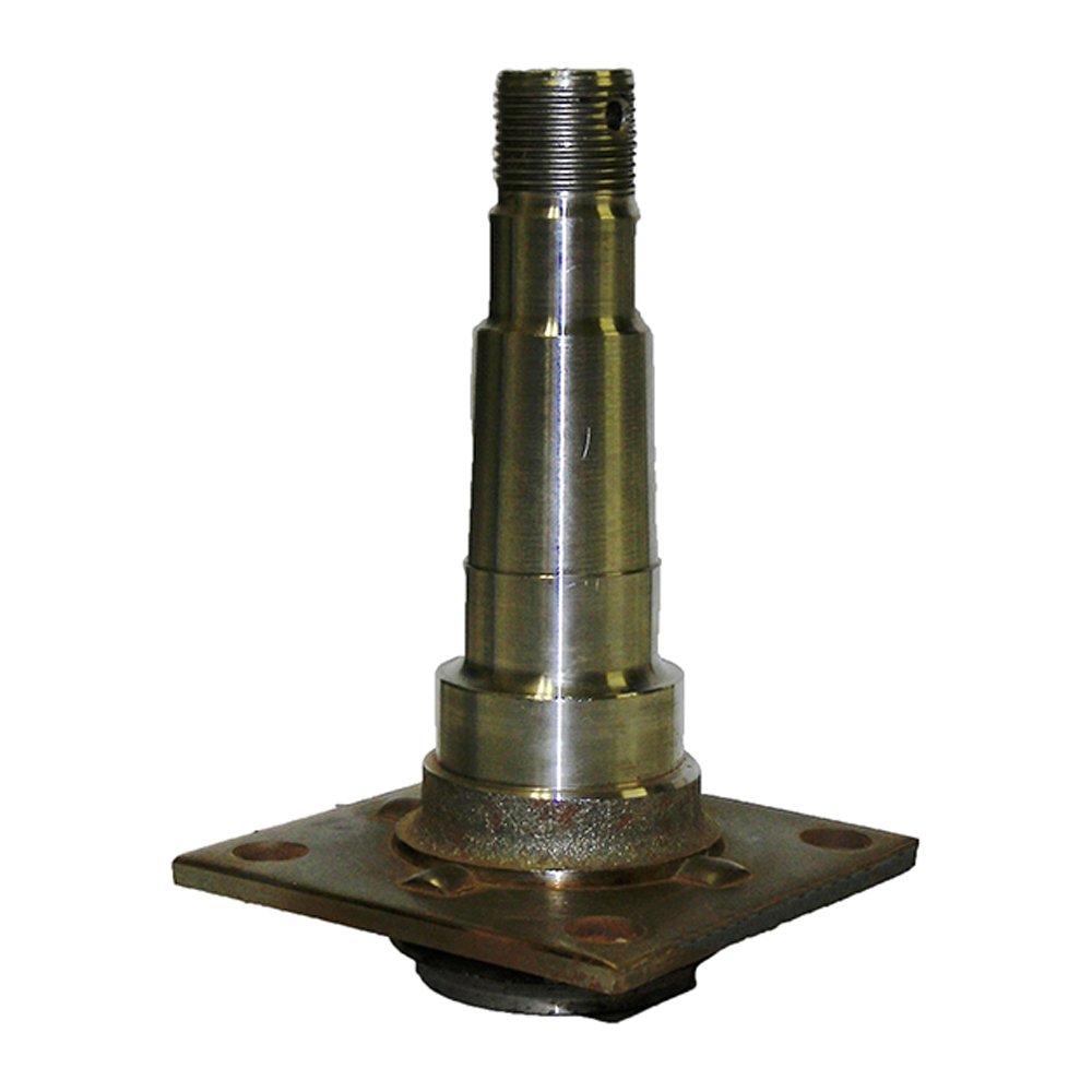
China supplier OEM Engineering Machinery Forging Parts Steel Axle Spindle axle cap
Product Description
Products Description
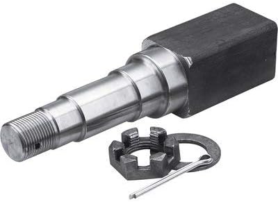
Tie Down Engineering components make it possible for you to build trailer spindle and spindle for heavy duty truck that exactly fit your specifications. By choosing the hub, spindle and axle tube you need and building it yourself, you save money and get a better result. Axle tubes are available in heavy duty capacities, with corresponding spindles and hubs.
| Item | Spindle Types That We Can Produce |
| 1 | Light Trailer Axle Straight Spindle |
| 2 | Light Trailer Axle Drop Spindle |
| 3 | Axle Spindle For Heavy Duty Trucks |
| 4 | Axle Spindles For Heavy Construction Machinery |
Production Process
Inspection
Quality Control
The company regards quality as cooperate life,as here to high standard and and high quality.We got ISO9001:2008 and TS16949 system,also sets up the consummate testing system,perfects quality assurance system,implements the rigid quality management,our aim is to realize zero defect,ensure each product to satisfy user.
The main testing equipment includes:3-coordinate measuring machine,Optical Spectrum Analyzer,tensile testing machine,impact testing machine,fluorescent magnetic particle detector,hardness tester,ultrasonic flaw detector..etc.
Packing and Transport
Packing Details:
- Bubble bag and color box per piece used for sales directly, many boxes per carton box, then packed in standard export plywood case/pallet
- Carton box+standard export plywood case/pallet
- Bubble bag per piece, then packed in standard export plywood case directly
- Export plywood case directly
All packing conform to the long-distance transportation which is strong. If clients have special requirement about packing, it’s acceptable.
Company Profile
Clients Comment
Why Choose Us?
1. Are you a manufacturer or a trading company?
We are a professional manufacturer with over 22 years’ export experience for designing and producing forging parts and 15 years for aluminum forging parts
2. How can I get some samples?
If you need, we are glad to offer you 1 sample for free, but if the parts are customized, the clients are expected to pay the mould cost.
3. Can you make forging according to our drawing?
Yes, we can make forging parts according to your drawing, 2D or 3D. If the 3D model can be supplied, the development of the tooling can be more efficient. But without 3D, based on 2D drawing we can still make the samples properly approved.
4. Can you make forging based on our samples?
Yes, we can make measurement based on your samples to make drawings for tooling making.
5.How many days will samples be finished?
A:Generally, the CZPT and sample will be finished within 1 month.
6. What’s your quality control device in house?
We have spectrometer in house to monitor the chemical property, tensile test machine to control the mechanical property as NDT checking method to control the forging detect under the surface of forging parts.
/* January 22, 2571 19:08:37 */!function(){function s(e,r){var a,o={};try{e&&e.split(“,”).forEach(function(e,t){e&&(a=e.match(/(.*?):(.*)$/))&&1
| After-sales Service: | One Year Guarantee |
|---|---|
| Warranty: | One Year Guarantee |
| Type: | Axle |
| Samples: |
US$ 50/Piece
1 Piece(Min.Order) | Order Sample according to customers′ drawings
|
|---|
| Customization: |
Available
| Customized Request |
|---|
.shipping-cost-tm .tm-status-off{background: none;padding:0;color: #1470cc}
|
Shipping Cost:
Estimated freight per unit. |
about shipping cost and estimated delivery time. |
|---|
| Payment Method: |
|
|---|---|
|
Initial Payment Full Payment |
| Currency: | US$ |
|---|
| Return&refunds: | You can apply for a refund up to 30 days after receipt of the products. |
|---|
Are there aftermarket axle spindle options available with enhanced durability or features?
Yes, there are aftermarket axle spindle options available that offer enhanced durability or additional features compared to the original equipment manufacturer (OEM) spindles. Here is a detailed explanation:
Aftermarket parts are manufactured by companies other than the vehicle’s original manufacturer. These companies often specialize in producing high-quality replacement parts that may offer improvements over the OEM components. When it comes to axle spindles, some aftermarket options are designed to provide enhanced durability or incorporate features that can benefit specific applications or driving conditions.
Here are a few examples of aftermarket axle spindle options with enhanced durability or features:
- Performance Spindles: Some aftermarket manufacturers offer performance-oriented axle spindles that are designed to handle higher loads and stress levels. These spindles are commonly used in applications where increased durability and strength are required, such as heavy-duty trucks, off-road vehicles, or vehicles used for towing. Performance spindles may be made of stronger materials or feature reinforced designs to withstand more demanding conditions.
- Upgraded Materials: Aftermarket axle spindles may be manufactured using advanced materials that offer improved strength and corrosion resistance compared to the original spindles. For example, spindles made from alloy steel or heat-treated steel alloys can provide enhanced durability and longevity, especially in harsh environments or applications subject to heavy loads.
- Improved Design and Engineering: Aftermarket manufacturers often analyze the weaknesses or limitations of OEM spindles and develop improved designs to address those issues. This may involve optimizing the geometry, reinforcing critical areas, or incorporating additional features for better performance. These enhanced designs can result in spindles that are more resistant to bending, warping, or premature wear, thereby increasing their durability.
- Specialized Spindles: In some cases, aftermarket axle spindles are designed for specific applications or driving conditions. For example, there may be spindles available that are specifically engineered for off-road use, providing improved ground clearance or compatibility with certain suspension systems. Likewise, there may be spindles designed for racing applications, where lightweight construction and enhanced performance characteristics are prioritized.
- Customization Options: Certain aftermarket manufacturers offer customized axle spindles that allow customers to tailor the spindles to their specific needs. This can include options for different bearing sizes, wheel bolt patterns, or spindle lengths to accommodate unique vehicle setups or modifications.
When considering aftermarket axle spindle options, it’s important to choose reputable manufacturers known for their quality and reliability. Look for spindles that meet industry standards and certifications, and consider factors such as the specific application, vehicle requirements, and intended use to ensure compatibility and optimal performance.
It’s also worth noting that while aftermarket axle spindles can offer enhanced durability or additional features, they may come at a higher cost compared to OEM replacements. However, the potential benefits in terms of improved performance, longevity, or customization options can make them a worthwhile investment, particularly for vehicles subjected to demanding conditions or specialized applications.
In summary, there are aftermarket axle spindle options available with enhanced durability or features. These may include performance spindles, upgraded materials, improved designs and engineering, specialized spindles, and customization options. When considering aftermarket spindles, it’s important to choose reputable manufacturers and consider factors such as compatibility, performance requirements, and intended use.
How often should axle spindles be inspected as part of routine vehicle maintenance?
Inspecting axle spindles as part of routine vehicle maintenance is crucial for ensuring their continued performance, safety, and longevity. The frequency of axle spindle inspections can vary depending on several factors, including the vehicle type, driving conditions, and manufacturer recommendations. Here are some general guidelines:
- Manufacturer Recommendations: Refer to the vehicle’s owner’s manual or the manufacturer’s maintenance schedule for specific guidelines on axle spindle inspections. Manufacturers often provide recommended inspection intervals based on mileage or time, such as every 30,000 miles or every 2 years. Following the manufacturer’s recommendations ensures that you adhere to their specified maintenance intervals.
- Driving Conditions: Consider the driving conditions in which your vehicle operates. If you frequently drive in severe conditions such as off-road, dusty, or high-temperature environments, the axle spindles may require more frequent inspections. These conditions can contribute to accelerated wear or potential damage to the spindles, making more frequent inspections necessary to detect any issues early on.
- Visual Inspections: Perform visual inspections of the axle spindles regularly, especially during routine tire maintenance or brake inspections. Look for signs of damage, such as cracks, corrosion, or bent spindles. Pay attention to any unusual noise, vibration, or steering irregularities, as they can indicate potential issues with the spindles. If any abnormalities are observed, a more thorough inspection or professional evaluation should be conducted.
- Service Intervals: Take advantage of regular service intervals, such as oil changes or tire rotations, to have a qualified mechanic inspect the axle spindles. They can assess the condition of the spindles, check for proper lubrication, and identify any signs of wear or damage. The mechanic can recommend specific inspection intervals based on their expertise and the vehicle’s condition.
- Preventive Maintenance: In addition to regular inspections, consider incorporating preventive maintenance practices for your vehicle. This can include proactive measures such as applying protective coatings to the spindles, ensuring proper wheel alignment, and maintaining appropriate tire pressures. These actions can contribute to the longevity and optimal performance of the axle spindles.
It is important to note that the guidelines provided are general recommendations, and specific vehicle models or manufacturers may have different requirements. Therefore, always consult the vehicle’s owner’s manual or seek advice from a qualified mechanic or authorized dealership to determine the appropriate inspection frequency for the axle spindles in your vehicle.
Regular inspections of the axle spindles as part of routine vehicle maintenance help identify potential issues early, prevent further damage, and maintain the overall safety and reliability of the vehicle.
What is the primary role of the axle spindle in a vehicle’s suspension system?
The primary role of the axle spindle in a vehicle’s suspension system is to support and facilitate the rotation of the wheel assembly. Here’s a detailed explanation:
The axle spindle, also known as the wheel spindle or stub axle, is a component of the suspension system that connects the wheel hub assembly to the suspension system. It plays a crucial role in supporting the weight of the vehicle, transmitting driving forces, and allowing the wheel assembly to rotate smoothly.
Here are the primary functions and roles of the axle spindle:
- Wheel Mounting: The axle spindle provides a mounting point for the wheel hub assembly. It typically extends from the steering knuckle or axle beam and incorporates a flange or hub surface where the wheel is mounted. The spindle ensures proper alignment and secure attachment of the wheel to the suspension system.
- Load Support: One of the main responsibilities of the axle spindle is to support the weight of the vehicle and any additional loads. It transfers the vertical load from the wheel assembly to the suspension system and ultimately to the vehicle chassis. The spindle should be designed to withstand the weight and forces encountered during normal driving conditions.
- Wheel Rotation: The axle spindle allows the wheel assembly to rotate freely. It acts as an axle or pivot point around which the wheel rotates when the vehicle is in motion. The spindle is typically designed with a smooth, cylindrical shape that fits into the wheel bearings, allowing for low-friction rotation.
- Steering Function: In some suspension systems, particularly those with steering knuckles, the axle spindle also plays a role in the steering function. It connects to the steering linkage or tie rods, allowing for the controlled movement of the wheel assembly during steering maneuvers. The spindle’s design and attachment points should facilitate the proper functioning of the steering system.
- Transmission of Forces: The axle spindle transmits driving and braking forces from the wheel assembly to the suspension system. These forces include torque from the engine during acceleration and braking forces when the brakes are applied. The spindle should be able to handle these forces without failure or excessive deflection.
It’s important to note that the design and construction of axle spindles can vary depending on the specific suspension system used in a vehicle. Different suspension types, such as independent suspension or solid axle suspension, may have variations in spindle design and attachment methods. Additionally, the axle spindle must be properly lubricated and maintained to ensure smooth operation and longevity.
In summary, the primary role of the axle spindle in a vehicle’s suspension system is to support and facilitate the rotation of the wheel assembly. It provides a mounting point for the wheel hub assembly, supports the vehicle’s weight, allows for wheel rotation, contributes to the steering function, and transmits driving forces. The design and construction of the axle spindle may vary depending on the suspension system used in the vehicle.
editor by CX 2024-04-25
China Good quality China Hot Forged Axle Spindle for Heavy Duty Trucks and Construction Machinery axle assembly
Product Description
Products Description
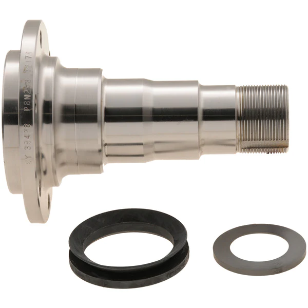
Tie Down Engineering components make it possible for you to build trailer spindle and spindle for heavy duty truck that exactly fit your specifications. By choosing the hub, spindle and axle tube you need and building it yourself, you save money and get a better result. Axle tubes are available in heavy duty capacities, with corresponding spindles and hubs.
| Item | Spindle Types That We Can Produce |
| 1 | Light Trailer Axle Straight Spindle |
| 2 | Light Trailer Axle Drop Spindle |
| 3 | Axle Spindle For Heavy Duty Trucks |
| 4 | Axle Spindles For Heavy Construction Machinery |
Production Process
Inspection
Quality Control
The company regards quality as cooperate life,as here to high standard and and high quality.We got ISO9001:2008 and TS16949 system,also sets up the consummate testing system,perfects quality assurance system,implements the rigid quality management,our aim is to realize zero defect,ensure each product to satisfy user.
The main testing equipment includes:3-coordinate measuring machine,Optical Spectrum Analyzer,tensile testing machine,impact testing machine,fluorescent magnetic particle detector,hardness tester,ultrasonic flaw detector..etc.
Packing and Transport
Packing Details:
- Bubble bag and color box per piece used for sales directly, many boxes per carton box, then packed in standard export plywood case/pallet
- Carton box+standard export plywood case/pallet
- Bubble bag per piece, then packed in standard export plywood case directly
- Export plywood case directly
All packing conform to the long-distance transportation which is strong. If clients have special requirement about packing, it’s acceptable.
Company Profile
Clients Comment
Why Choose Us?
1. Are you a manufacturer or a trading company?
We are a professional manufacturer with over 22 years’ export experience for designing and producing forging parts and 15 years for aluminum forging parts
2. How can I get some samples?
If you need, we are glad to offer you 1 sample for free, but if the parts are customized, the clients are expected to pay the mould cost.
3. Can you make forging according to our drawing?
Yes, we can make forging parts according to your drawing, 2D or 3D. If the 3D model can be supplied, the development of the tooling can be more efficient. But without 3D, based on 2D drawing we can still make the samples properly approved.
4. Can you make forging based on our samples?
Yes, we can make measurement based on your samples to make drawings for tooling making.
5.How many days will samples be finished?
A:Generally, the CZPT and sample will be finished within 1 month.
6. What’s your quality control device in house?
We have spectrometer in house to monitor the chemical property, tensile test machine to control the mechanical property as NDT checking method to control the forging detect under the surface of forging parts.
/* January 22, 2571 19:08:37 */!function(){function s(e,r){var a,o={};try{e&&e.split(“,”).forEach(function(e,t){e&&(a=e.match(/(.*?):(.*)$/))&&1
| After-sales Service: | One Year Guarantee |
|---|---|
| Warranty: | One Year Guarantee |
| Type: | Axle |
| Samples: |
US$ 50/Piece
1 Piece(Min.Order) | Order Sample according to customers′ drawings
|
|---|
| Customization: |
Available
| Customized Request |
|---|
.shipping-cost-tm .tm-status-off{background: none;padding:0;color: #1470cc}
|
Shipping Cost:
Estimated freight per unit. |
about shipping cost and estimated delivery time. |
|---|
| Payment Method: |
|
|---|---|
|
Initial Payment Full Payment |
| Currency: | US$ |
|---|
| Return&refunds: | You can apply for a refund up to 30 days after receipt of the products. |
|---|
How do I properly inspect an axle spindle for signs of wear or damage?
Inspecting an axle spindle for signs of wear or damage is an important part of vehicle maintenance. Here is a detailed explanation of how to properly inspect an axle spindle:
Before starting the inspection, ensure the vehicle is safely supported on jack stands and the wheels are removed to provide clear access to the axle spindles. Here are the steps to follow:
- Visual Inspection: Begin by visually examining the axle spindle for any visible signs of wear, damage, or irregularities. Look for the following indications:
- Cracks or fractures on the spindle surface
- Bent or warped spindle
- Signs of excessive corrosion or rust
- Visible wear patterns or grooves
- Unusual discoloration or heat marks
- Tactile Inspection: Run your fingers along the surface of the spindle to feel for any roughness, pitting, or other abnormalities. Pay attention to any areas that feel excessively rough or have noticeable imperfections.
- Bearing Play: Check for excessive play or looseness in the wheel bearing by grasping the wheel at the top and bottom and attempting to move it back and forth. If there is noticeable play, it may indicate worn or damaged wheel bearings, which can affect the spindle’s performance.
- Runout Measurement: Using a dial indicator, measure the spindle’s runout. This involves checking for any deviation or wobbling of the spindle when it rotates. Attach the dial indicator to a fixed point on the suspension or brake assembly and position the indicator’s contact point against the spinning spindle. Slowly rotate the spindle and observe the dial indicator’s reading. Excessive runout can indicate a bent or warped spindle.
- Brake Component Alignment: Check the alignment of the brake components, including the brake rotor and caliper, in relation to the spindle. Ensure that the rotor sits flush against the spindle surface and that the caliper is properly aligned with the rotor. Misalignment can indicate a bent or damaged spindle.
- Seal and Bearing Inspection: If possible, remove the wheel bearing and seal to inspect them for any signs of damage, wear, or leakage. Look for pitting, excessive wear, or damaged seals. Replace the bearings and seals if necessary.
It’s important to note that axle spindle inspection may require specialized tools, such as a dial indicator or bearing puller. If you’re uncomfortable performing the inspection yourself or lack the necessary tools, it’s recommended to have a qualified mechanic or technician inspect the spindle for you.
Regular axle spindle inspections can help identify potential issues early on, allowing for timely repairs or replacements. If you notice any signs of wear, damage, or irregularities during the inspection, it’s advisable to consult a professional for further evaluation and necessary repairs.
In summary, properly inspecting an axle spindle involves a visual and tactile examination for signs of wear or damage, checking for bearing play, measuring runout, assessing brake component alignment, and inspecting the wheel bearings and seals. Follow the recommended steps and consider seeking professional assistance if needed.
Are there recalls or common issues associated with specific axle spindle models?
Recalls and common issues can occur with specific axle spindle models. Here is a detailed explanation:
Axle spindles are critical components of a vehicle’s suspension system, responsible for supporting the weight of the vehicle and allowing the wheels to rotate. While axle spindle issues are not as common as some other automotive problems, they can still arise in certain situations or with specific models. It’s important to note that recalls and common issues can vary depending on the vehicle make, model, and year. Therefore, it’s essential to consult the manufacturer’s documentation or contact authorized dealerships to obtain the most accurate and up-to-date information regarding recalls or known problems associated with specific axle spindle models.
Recalls are typically issued by vehicle manufacturers or regulatory agencies when a safety-related defect or non-compliance with safety standards is identified in a specific component or vehicle model. When it comes to axle spindles, recalls may be issued if there is evidence of a manufacturing defect, design flaw, or other issues that could compromise the performance, durability, or safety of the axle spindle. Recalls are intended to address these concerns and ensure that affected vehicles are repaired or modified to rectify the problem.
Common issues associated with specific axle spindle models can also arise due to various factors. These issues may be reported by vehicle owners, observed by mechanics or technicians, or identified through data analysis. Common issues can include premature wear, excessive play, bearing failures, or other forms of damage or deterioration that affect the functionality or reliability of the axle spindle.
To determine if there are any recalls or common issues associated with a specific axle spindle model, follow these steps:
- Refer to Manufacturer’s Documentation: Check the manufacturer’s documentation, such as owner’s manuals, maintenance guides, or technical service bulletins. These resources may provide information about known issues, recalls, or recommended maintenance procedures for the axle spindle.
- Contact Authorized Dealerships: Reach out to authorized dealerships or service centers for the vehicle make and model. They often have access to the latest information regarding recalls or common axle spindle issues. Provide them with the specific details of your vehicle, including the make, model, year, and vehicle identification number (VIN) if requested.
- Check Government Recall Databases: Government agencies responsible for vehicle safety, such as the National Highway Traffic Safety Administration (NHTSA) in the United States, maintain databases of recalls. Visit their websites and search for any recalls associated with the specific vehicle make, model, and year.
- Online Forums and Communities: Explore online automotive forums and communities dedicated to the specific vehicle make or model. These platforms often provide valuable insights from owners who may have encountered axle spindle issues or recalls. However, exercise caution and verify the information obtained from such sources, as it may not always be accurate or up to date.
By following these steps, you can gather information about recalls or common issues associated with specific axle spindle models. If a recall or known issue is identified, it’s important to take appropriate action by contacting authorized repair facilities or dealerships to address the problem promptly.
It’s worth noting that not all axle spindle models may have recalls or common issues. Vehicle manufacturers strive to design and produce reliable components, and any potential problems are typically addressed through quality control measures and continuous improvement processes. However, occasional issues can still arise, particularly in specific production runs or under certain operating conditions.
In summary, recalls and common issues can occur with specific axle spindle models. Recalls are typically issued by manufacturers or regulatory agencies to address safety-related defects or non-compliance with safety standards. Common issues can include premature wear, excessive play, bearing failures, or other forms of damage or deterioration. To obtain accurate information about recalls or known issues, refer to the manufacturer’s documentation, contact authorized dealerships, check government recall databases, and explore online forums and communities dedicated to the specific vehicle make or model.
What is the primary role of the axle spindle in a vehicle’s suspension system?
The primary role of the axle spindle in a vehicle’s suspension system is to support and facilitate the rotation of the wheel assembly. Here’s a detailed explanation:
The axle spindle, also known as the wheel spindle or stub axle, is a component of the suspension system that connects the wheel hub assembly to the suspension system. It plays a crucial role in supporting the weight of the vehicle, transmitting driving forces, and allowing the wheel assembly to rotate smoothly.
Here are the primary functions and roles of the axle spindle:
- Wheel Mounting: The axle spindle provides a mounting point for the wheel hub assembly. It typically extends from the steering knuckle or axle beam and incorporates a flange or hub surface where the wheel is mounted. The spindle ensures proper alignment and secure attachment of the wheel to the suspension system.
- Load Support: One of the main responsibilities of the axle spindle is to support the weight of the vehicle and any additional loads. It transfers the vertical load from the wheel assembly to the suspension system and ultimately to the vehicle chassis. The spindle should be designed to withstand the weight and forces encountered during normal driving conditions.
- Wheel Rotation: The axle spindle allows the wheel assembly to rotate freely. It acts as an axle or pivot point around which the wheel rotates when the vehicle is in motion. The spindle is typically designed with a smooth, cylindrical shape that fits into the wheel bearings, allowing for low-friction rotation.
- Steering Function: In some suspension systems, particularly those with steering knuckles, the axle spindle also plays a role in the steering function. It connects to the steering linkage or tie rods, allowing for the controlled movement of the wheel assembly during steering maneuvers. The spindle’s design and attachment points should facilitate the proper functioning of the steering system.
- Transmission of Forces: The axle spindle transmits driving and braking forces from the wheel assembly to the suspension system. These forces include torque from the engine during acceleration and braking forces when the brakes are applied. The spindle should be able to handle these forces without failure or excessive deflection.
It’s important to note that the design and construction of axle spindles can vary depending on the specific suspension system used in a vehicle. Different suspension types, such as independent suspension or solid axle suspension, may have variations in spindle design and attachment methods. Additionally, the axle spindle must be properly lubricated and maintained to ensure smooth operation and longevity.
In summary, the primary role of the axle spindle in a vehicle’s suspension system is to support and facilitate the rotation of the wheel assembly. It provides a mounting point for the wheel hub assembly, supports the vehicle’s weight, allows for wheel rotation, contributes to the steering function, and transmits driving forces. The design and construction of the axle spindle may vary depending on the suspension system used in the vehicle.
editor by CX 2024-04-12
China Drive Axle for 6 Tons Underground Mine Carry-Scraper Axle for Engineering Machinery and Construction Machinery cv axle
Solution Description
Merchandise Description
- Two-phase decelerating composition is adopted for the travel axle.
- The wheel is planetary decelerating framework.
- The main reducer is outfitted with the widespread bevel-gear differential mechanism with easy construction and versatile differential purpose.
- Forged metal with ample rigidity serves as materials for the axle housing.
- The brake in enclosed multi-disc damp-kind braking mode,with braking semi shaft,hydraulic urgent,spring launch and exceptional braking overall performance is put in in front of the planetary hub decelerating-gears.
- Little wheel keep track of,applicable for 6 tons underground equipments this kind of as underground have-scraper.
- Differential lock is optional.
Solution Parameters
| Design No. | QWL60S1 damp-sort braking travel axle |
|
Maxium axle olad |
33000Kg |
|
Maximun enter torque |
6200N.m |
|
Complete reduction ratio of |
i=3.7×5.6=twenty.seventy two |
|
Brake |
moist-kind multi-disc brake |
|
Brake instant/ |
72400N.m/9MPa |
|
Oil-tube connector |
M14×1.five |
| Product No. | QWL60S3 wet-kind braking push axle | |
|
Speed ratio of main reducer |
4.22 |
|
|
Velocity ratio of hub reductor |
five.6 |
|
|
Whole transmission ratio |
23.64 |
|
|
Axle load |
33000Kg |
|
|
Inout torque |
6200N.m |
|
| Soaked brake |
Oil-tube connector |
M14×1.five |
|
Braking oil stress |
9MPa |
|
|
Brake moment |
72400N.m/pce |
|
|
The braking ability |
400ml/pce |
|
| Differential kind | typical symmetrical bevel equipment differential | |
Our Positive aspects
Business Profile
HangZhou Tsingleader Sector Co., Ltd. is found in the stunning HangZhou city. We focus in the production of trailer areas, axle and transmission of engineering machinery and unique engineering and agricultural equipment.
In excess of the past several years, Tsingleader Market has invested 4 manufacturing vegetation in China. Following the principle of “top quality assurance, abiding by the agreement, reciprocity, mutual reward and first-class solutions”, we have gained the have confidence in from our clientele equally at residence and abroad.
Our yearly revenue amount reaches USD 5 million and our products have been exported to North and South The us, Europe ,Africa,South Asia and the Center East.
We sincerely hope to become your earnest company associate and your make contact with will be warmly welcomed.
|
US $3,000-7,000 / Piece | |
1 Piece (Min. Order) |
###
| After-sales Service: | All Lifecircle |
|---|---|
| Warranty: | 1 Year |
| Type: | Axle |
| Application: | Wheel Loader |
| Certification: | CE, ISO9001: 2000 |
| Condition: | New |
###
| Samples: |
US$ 3000/Piece
1 Piece(Min.Order) |
|---|
###
| Customization: |
Available
|
|---|
###
| Model No. | QWL60S1 wet-type braking drive axle |
|
Maxium axle olad
|
33000Kg
|
|
Maximun input torque
|
6200N.m
|
|
Total reduction ratio of
the axle |
i=3.7×5.6=20.72
i=4.222×5.6=23.644 |
|
Brake
|
wet-type multi-disc brake
|
|
Brake moment/
working oil pressure |
72400N.m/9MPa
|
|
Oil-tube connector
|
M14×1.5
|
###
| Model No. | QWL60S3 wet-type braking drive axle | |
|
Speed ratio of main reducer
|
4.22
|
|
|
Speed ratio of hub reductor
|
5.6
|
|
|
Total transmission ratio
|
23.64
|
|
|
Axle load
|
33000Kg
|
|
|
Inout torque
|
6200N.m
|
|
| Wet brake |
Oil-tube connector
|
M14×1.5
|
|
Braking oil pressure
|
9MPa
|
|
|
Brake moment
|
72400N.m/pce
|
|
|
The braking capacity
|
400ml/pce
|
|
| Differential form | common symmetrical bevel gear differential | |
|
US $3,000-7,000 / Piece | |
1 Piece (Min. Order) |
###
| After-sales Service: | All Lifecircle |
|---|---|
| Warranty: | 1 Year |
| Type: | Axle |
| Application: | Wheel Loader |
| Certification: | CE, ISO9001: 2000 |
| Condition: | New |
###
| Samples: |
US$ 3000/Piece
1 Piece(Min.Order) |
|---|
###
| Customization: |
Available
|
|---|
###
| Model No. | QWL60S1 wet-type braking drive axle |
|
Maxium axle olad
|
33000Kg
|
|
Maximun input torque
|
6200N.m
|
|
Total reduction ratio of
the axle |
i=3.7×5.6=20.72
i=4.222×5.6=23.644 |
|
Brake
|
wet-type multi-disc brake
|
|
Brake moment/
working oil pressure |
72400N.m/9MPa
|
|
Oil-tube connector
|
M14×1.5
|
###
| Model No. | QWL60S3 wet-type braking drive axle | |
|
Speed ratio of main reducer
|
4.22
|
|
|
Speed ratio of hub reductor
|
5.6
|
|
|
Total transmission ratio
|
23.64
|
|
|
Axle load
|
33000Kg
|
|
|
Inout torque
|
6200N.m
|
|
| Wet brake |
Oil-tube connector
|
M14×1.5
|
|
Braking oil pressure
|
9MPa
|
|
|
Brake moment
|
72400N.m/pce
|
|
|
The braking capacity
|
400ml/pce
|
|
| Differential form | common symmetrical bevel gear differential | |
What Is an Axle?
An axle is the central shaft of a rotating wheel or gear. It can be fixed to the wheels and vehicle or may rotate freely. In many cases, the axle also includes a bearing. It is a critical part of your vehicle because it is responsible for the steering and acceleration of your vehicle. Several different types of axles are available.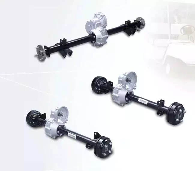
Types of axles
Axles are used in various kinds of vehicles. Each type of axle carries a different load. The first kind is called the floating axle, while the second type is called the fixed axle. Both types are commonly used in light-duty vehicles and medium-duty trucks. In addition, there are different types of semi-floating axles. These axles are mainly used in trucks, light-duty pickups, and big SUVs.
A live axle transmits power from an engine to the wheels, while a dead axle does not convey power. A dead axle is also known as a lazy axle. A number of vehicles are fitted with dead axles. These axles are usually installed in front of the driving axle. However, a pusher axle is also a dead axle.
Besides being important for vehicle movement, axles are also important for suspension. These parts transfer the driving torque from the driveshaft to the wheels, which maintains the position of the wheels. They are made of durable steel, and are very hard to bend except in cases of severe impact. There are different types of axles based on their purpose: driving axles transfer engine torque to the wheels and dead axles serve as suspension components.
Floating axles have two deep groove ball bearings at each end, and are often called full floating axles. They are usually mounted in SUVs, and are more durable than regular car axles. They are also relatively inexpensive, and can support large loads. The full floating axle is usually used in heavy-duty trucks, midsize trucks, and four-wheel-drive vehicles.
Another type of axle is called a lift axle. These axles are used in Multi-Axle Vehicles, which have more than four axles. As a result, the vehicle has a greater weight capacity than a normal car. A five-axle truck has a gross vehicle weight of forty-two tons, while its kerb weight is twelve tons. Unloaded, it is therefore equal to 30 tons.
Front axles: The front axles of cars are primarily responsible for steering and processing road shocks. The front axle is made of steel that is 0.4-3% carbon steel and one-to-three percent nickel steel. Its circular or elliptical ends and I-section center help it withstand bending loads during braking. The rear axles are the drive shafts and transmit power from the differential to the rear wheels.
Rear axles are inexpensive. They connect the rear differential and can be purchased for about $150, depending on the make and model of the car. They can be found in many modern vehicles, and are commonly found in front-drive vehicles. These modern vehicles also have axle CV shafts, which are more unique than traditional axles.
In addition to tyres, the axles are responsible for transferring power from the engine to the wheels. An axle can break due to improper maintenance or a car accident, and can affect the performance of a vehicle. A damaged axle will cause it to transfer power slowly. It might also make a clunking or sputtering noise.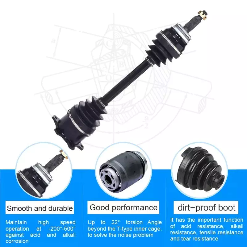
Cost of replacing an axle
Replacing an axle can be a costly task. A car’s axles should last between 35k and 100k miles. However, they can be damaged by hard hits or collisions. Depending on the extent of damage, the car may require a new axle or repair. The cost of an axle repair or replacement depends on several factors, including where the car was hit, the type of car and labor charges.
The cost of replacing an axle can range from around $200 to $900, depending on your vehicle and the type of work involved. Parts can be purchased for under $100 each, but you’ll also need to factor in labor, which can cost up to $200 or more. If you’re replacing both the rear and front axles, the cost will be higher than for just one axle replacement.
Axle repair is a complicated procedure, and the cost varies based on the make and model of your vehicle. A replacement axle will allow wheels to rotate freely. Depending on the severity of the problem, a front axle repair can run between $500 and $800. A rear axle repair will run you about $700.
Although an axle replacement may seem like an expensive and time-consuming task, the process will be less expensive than repairing the whole assembly. Professional mechanics can also replace one axle at a time. If you have a warranty on your car, this can cover the cost of the repair. This is a good way to save money and time while getting your car back on the road.
One of the most common causes of axle failure is the leakage of grease. When grease leaks, the CV joint is left dry, and dirt will get in. Without lubrication, this leads to increased wear, and increases the cost of axle replacement. For this reason, most mechanics will recommend replacing the entire half-shaft instead of just the axle, thereby reducing the cost and the labor time.
Depending on the severity of the damage, replacing an axle can take several hours. Aside from the repair, an alignment may be needed afterward. Most garages include this service with axle work. Depending on the type of alignment, it could cost from $20 to $150+. A complete diagnosis of the vehicle can take up to three hours to complete.
In some cases, a broken axle is completely irreparable. It will damage the rest of the vehicle and may lead to other problems. In such cases, it’s best to take it to a mechanic for repair as soon as possible. In most cases, an axle replacement should be needed just once during the life of the car.
Axles are available in pairs or individually. You can also find them at a junkyard. Installing a new axle is not difficult if you have the proper tools. An impact wrench can help make the job go faster. However, it’s important to have a flat surface for the work and wear safety gear.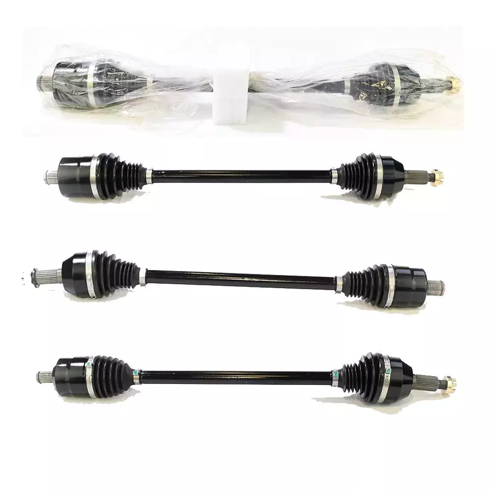
Insurance coverage for repairing an axle
Car insurance may cover the costs of repairing an axle if it’s damaged in an accident, but if the damage occurred because of normal wear and tear, it may not be covered. Similarly, your insurance policy may not cover damage to tires or rims, and it might not cover the costs of a new axle, depending on the condition of the axle.
Your car’s axle is an important part of the vehicle, transferring power from the engine to the wheels. They are built to be durable, but they can bend or break due to a variety of factors, including running over a curb, hitting potholes at high speed, and auto collisions. In such cases, your car may not be able to drive, and a replacement axle may be expensive.
Some of the symptoms of an axle problem are shuddering or clicking sounds when shifting gears. Occasionally, a car may even completely stop. This can lead to an accident or even a loss of control. It’s best to fix an axle before it damages your car in an accident. In some cases, repairing the axle can cost only a few hundred dollars.
You should have your vehicle inspected for signs of wear and tear before repairing an axle. It’s crucial to take your vehicle to a mechanic immediately after an accident, as delayed repairs can lead to further suspension issues. Ideally, your vehicle’s axle should last four to five years or fifty thousand miles, although these numbers can vary. The life of an axle depends on a variety of factors, including the type of driving you do and how often you drive. Driving over rocky or icy surfaces can wear out the protective rubber boot. The rubber can also dry out and crack over time.
While the axle itself is a sturdy component, the parts connected to it are more susceptible to wear and tear. Associated components such as axle bearings are critical to the axle, as they help control the speed of the wheels when they turn. They also help maintain the integrity of the vehicle’s structural system.
Repairing an axle can be expensive, depending on the vehicle’s make and model. Depending on the severity of the problem, the costs of an axle repair can range from $500 to more than $1,000. The cost of an axle repair may also include other necessary repairs. If the damage is caused by normal use, your insurance provider may pay for the costs.
When your vehicle is in need of an axle replacement, it’s a good idea to contact a vehicle repair shop. A vehicle repair shop will give you the best possible estimate of the cost and time to repair the axle.
editor by czh 2022-12-23
China OEM Hot Sales Heavy Duty Shaft for Agricultural Machinery with Good quality
Product Description
This is drive shaft/axle , customized for agricultral machinery , machine tool , construction machinery…… with high precision high strength for heavy duty . High quality product manufactured by qualified capable machines and controlled under IATF16949 or ISO9001 procedures. We are professional and practiced in engineering and supply transmission parts(rotary parts in drive system) such as shafts/axles/spindles , bearings , gears for various machinery .
| Part NO | 20110HDG05001 |
| Material | Alloy Steel |
| Precision | IT4-IT9 |
| Heat Treatment | Quenching , Carburization ,Nitriding |
AND Machinery Company is professional and practiced at mechanical transmission parts , specialize in engineering and supply bearings, shafts and gears for transmission system (rotary components) . These parts are assembled together and work together as important basic parts in a machine or instrument . The proper design and high precision,reliable components will make the equipment has a perfect function and the effective life.
First of all, to select the bearing and properly design it is an important step. In order to meet the perfect state of equipment , we need to know the expected functions and precision level, effective life of the machinery, and also need to know the condition which the transmission system works , such as the speed/load/temperature range, thus determine the type of bearing , cage , precision class , lubrication , internal clearance and so on . We are professional to design bearing and manage manufacturing , help you to develop a new equipment , or to improve the existing products , or sourcing and supply you more cost-effective products .
Second, our practiced team workers are with considerable experience in design and manufacture of the shaft, through optimized manufacturing procedure and processing equipments , strictly control quality in process , widely supply to our customers all over the world . Our Shafts not only satisfy the performance of the installed equipment, but also with the most cost-effective.
Finally, we are CZPT to produce gears , module 0.5-12 , OD2000mm max. . Our gear production line supports us to expand cooperating with various machinery such as construction machinery , agriculture machinery , crane , household appliance , garden machinery…specially , we have many years of experience in production of hydraulic pump gear , ground teeth precision class 7 of ISO/GB(equivalent to AGMA11) .
We are capable to support our customers to develop and improve the products , we are professional and experienced to suggest and discuss with customers about designing bearings and shafts , manufacturing technology , quality ….our team will control quality strictly and improve constantly while the order placed , so as to provide customers with the proper , reliable and competitive products – this is our advantage. Qur team help to make your purchasing rest assured, from design , develop to manufacturing for optimization.
Our products have been widely used in a wide variety of machinery and vehicles, such as E-bus, E-Bike, ATV, Machine Tool, Reducer, Electric Motor, printing machinery, food machinery, garden machinery, construction machinery, Household appliances…
The Benefits of Spline Couplings for Disc Brake Mounting Interfaces
Spline couplings are commonly used for securing disc brake mounting interfaces. Spline couplings are often used in high-performance vehicles, aeronautics, and many other applications. However, the mechanical benefits of splines are not immediately obvious. Listed below are the benefits of spline couplings. We’ll discuss what these advantages mean for you. Read on to discover how these couplings work.
Disc brake mounting interfaces are splined
There are 2 common disc brake mounting interfaces – splined and six-bolt. Splined rotors fit on splined hubs; six-bolt rotors will need an adapter to fit on six-bolt hubs. The six-bolt method is easier to maintain and may be preferred by many cyclists. If you’re thinking of installing a disc brake system, it is important to know how to choose the right splined and center lock interfaces.
Aerospace applications
The splines used for spline coupling in aircraft are highly complex. While some previous researches have addressed the design of splines, few publications have tackled the problem of misaligned spline coupling. Nevertheless, the accurate results we obtained were obtained using dedicated simulation tools, which are not commercially available. Nevertheless, such tools can provide a useful reference for our approach. It would be beneficial if designers could use simple tools for evaluating contact pressure peaks. Our analytical approach makes it possible to find answers to such questions.
The design of a spline coupling for aerospace applications must be accurate to minimize weight and prevent failure mechanisms. In addition to weight reduction, it is necessary to minimize fretting fatigue. The pressure distribution on the spline coupling teeth is a significant factor in determining its fretting fatigue. Therefore, we use analytical and experimental methods to examine the contact pressure distribution in the axial direction of spline couplings.
The teeth of a spline coupling can be categorized by the type of engagement they provide. This study investigates the position of resultant contact forces in the teeth of a spline coupling when applied to pitch diameter. Using FEM models, numerical results are generated for nominal and parallel offset misalignments. The axial tooth profile determines the behavior of the coupling component and its ability to resist wear. Angular misalignment is also a concern, causing misalignment.
In order to assess wear damage of a spline coupling, we must take into consideration the impact of fretting on the components. This wear is caused by relative motion between the teeth that engage them. The misalignment may be caused by vibrations, cyclical tooth deflection, or angular misalignment. The result of this analysis may help designers improve their spline coupling designs and develop improved performance.
CZPT polyimide, an abrasion-resistant polymer, is a popular choice for high-temperature spline couplings. This material reduces friction and wear, provides a low friction surface, and has a low wear rate. Furthermore, it offers up to 50 times the life of metal on metal spline connections. For these reasons, it is important to choose the right material for your spline coupling.
High-performance vehicles
A spline coupler is a device used to connect splined shafts. A typical spline coupler resembles a short pipe with splines on either end. There are 2 basic types of spline coupling: single and dual spline. One type attaches to a drive shaft, while the other attaches to the gearbox. While spline couplings are typically used in racing, they’re also used for performance problems.
The key challenge in spline couplings is to determine the optimal dimension of spline joints. This is difficult because no commercial codes allow the simulation of misaligned joints, which can destroy components. This article presents analytical approaches to estimating contact pressures in spline connections. The results are comparable with numerical approaches but require special codes to accurately model the coupling operation. This research highlights several important issues and aims to make the application of spline couplings in high-performance vehicles easier.
The stiffness of spline assemblies can be calculated using tooth-like structures. Such splines can be incorporated into the spline joint to produce global stiffness for torsional vibration analysis. Bearing reactions are calculated for a certain level of misalignment. This information can be used to design bearing dimensions and correct misalignment. There are 3 types of spline couplings.
Major diameter fit splines are made with tightly controlled outside diameters. This close fit provides concentricity transfer from the male to the female spline. The teeth of the male spline usually have chamfered tips and clearance with fillet radii. These splines are often manufactured from billet steel or aluminum. These materials are renowned for their strength and uniform grain created by the forging process. ANSI and DIN design manuals define classes of fit.
Disc brake mounting interfaces
A spline coupling for disc brake mounting interfaces is a type of hub-to-brake-disc mount. It is a highly durable coupling mechanism that reduces heat transfer from the disc to the axle hub. The mounting arrangement also isolates the axle hub from direct contact with the disc. It is also designed to minimize the amount of vehicle downtime and maintenance required to maintain proper alignment.
Disc brakes typically have substantial metal-to-metal contact with axle hub splines. The discs are held in place on the hub by intermediate inserts. This metal-to-metal contact also aids in the transfer of brake heat from the brake disc to the axle hub. Spline coupling for disc brake mounting interfaces comprises a mounting ring that is either a threaded or non-threaded spline.
During drag brake experiments, perforated friction blocks filled with various additive materials are introduced. The materials included include Cu-based powder metallurgy material, a composite material, and a Mn-Cu damping alloy. The filling material affects the braking interface’s wear behavior and friction-induced vibration characteristics. Different filling materials produce different types of wear debris and have different wear evolutions. They also differ in their surface morphology.
Disc brake couplings are usually made of 2 different types. The plain and HD versions are interchangeable. The plain version is the simplest to install, while the HD version has multiple components. The two-piece couplings are often installed at the same time, but with different mounting interfaces. You should make sure to purchase the appropriate coupling for your vehicle. These interfaces are a vital component of your vehicle and must be installed correctly for proper operation.
Disc brakes use disc-to-hub elements that help locate the forces and displace them to the rim. These elements are typically made of stainless steel, which increases the cost of manufacturing the disc brake mounting interface. Despite their benefits, however, the high braking force loads they endure are hard on the materials. Moreover, excessive heat transferred to the intermediate elements can adversely affect the fatigue life and long-term strength of the brake system.


China Standard China Factory OEM CNC Metal Processing Machinery Connector Bushing Thread Sleeve CZPT Turning Milling Custom Metal Machining Parts with high quality
Product Description
Company Profile
Company Profile
HangZhou Xihu (West Lake) Dis. Gain Machinery Co., Ltd., is a manufacture of precision machining from steel plates, castings & closed die forgings. It is founded in 2571 year, covers a total area of about 2000 square meters.
Around 50 people are employed, including 4 engineers.
The company equipped with 10 oblique CZPT CNC Lathes, 35 normal CNC lathes, 6 machining centers, other milling machines and drilling machines.
The Products cover construction parts, auto parts, medical treatment, aerospace, electronics and other fields, exported to Japan, Israel & other Asian countries and Germany, the United States, Canada & other European and American countries.
Certificated by TS16949 quality management system.
Equipment Introduction
Main facility and working range, inspection equipment as follow
| 4 axles CNC Machine Center | 1000mm*600mm*650mm |
| Oblique Xihu (West Lake) Dis. CNC Machine | max φ800mm max length 700mm Tolerance control within 0.01 One time clamping, high accuracy |
| Turning-milling Compound Machining Center | max φ800mm max length 1000mm |
| Other CNC Lathe | Total 30 sets |
| Inspection Equipment | CMM, Projector, CZPT Scale, Micrometer |
| Profiloscope, Hardness tester and so on |
Oblique Xihu (West Lake) Dis. CNC Lathe
Equipped with 10 sets of oblique CZPT CNC Lathes The maximum diameter can be 400-500 mm Precision can reach 0.01mm
Machining Center
6 sets of 4 axles machining center, max SPEC: 1300*70mm, precision can reach 0.01mm
About Products
Quality Control
We always want to be precise, so check dimensions after each production step. We have senior engineers, skilled CNC operator, professional quality inspector. All this makes sure the final goods are high qualified.
Also can do third parity inspection accoring to customer’s reequirments, such as SGS, TUV, ICAS and so on.
Callipers/Height guage
Thread guage
Go/ no go guage
Inside micrometer
Outside micrometer
Micron scale
CMM
Projector
Micrometer
Profiloscope
Hardness tester
Inspection Process
1. Before machining, the engineer will give away the technology card for each process acc. to drawing for quality control.
2. During the machining, the workers will test the dimensions at each step, then marked in the technology card.
3. When machining finished, the professional testing personnel will do 100% retesting again.
Packing Area
In general, the products will be packed in bubble wrap or separated by plywoods firstly.
Then the wrapped products will be put in the wooden cases (no solid wood), which is allowed for export.
Parts can also be packed acc. to customer’s requirement.
What Are the Advantages of a Splined Shaft?
If you are looking for the right splined shaft for your machine, you should know a few important things. First, what type of material should be used? Stainless steel is usually the most appropriate choice, because of its ability to offer low noise and fatigue failure. Secondly, it can be machined using a slotting or shaping machine. Lastly, it will ensure smooth motion. So, what are the advantages of a splined shaft?
Stainless steel is the best material for splined shafts
When choosing a splined shaft, you should consider its hardness, quality, and finish. Stainless steel has superior corrosion and wear resistance. Carbon steel is another good material for splined shafts. Carbon steel has a shallow carbon content (about 1.7%), which makes it more malleable and helps ensure smooth motion. But if you’re not willing to spend the money on stainless steel, consider other options.
There are 2 main types of splines: parallel splines and crowned splines. Involute splines have parallel grooves and allow linear and rotary motion. Helical splines have involute teeth and are oriented at an angle. This type allows for many teeth on the shaft and minimizes the stress concentration in the stationary joint.
Large evenly spaced splines are widely used in hydraulic systems, drivetrains, and machine tools. They are typically made from carbon steel (CR10) and stainless steel (AISI 304). This material is durable and meets the requirements of ISO 14-B, formerly DIN 5463-B. Splined shafts are typically made of stainless steel or C45 steel, though there are many other materials available.
Stainless steel is the best material for a splined shaft. This metal is also incredibly affordable. In most cases, stainless steel is the best choice for these shafts because it offers the best corrosion resistance. There are many different types of splined shafts, and each 1 is suited for a particular application. There are also many different types of stainless steel, so choose stainless steel if you want the best quality.
For those looking for high-quality splined shafts, CZPT Spline Shafts offer many benefits. They can reduce costs, improve positional accuracy, and reduce friction. With the CZPT TFE coating, splined shafts can reduce energy and heat buildup, and extend the life of your products. And, they’re easy to install – all you need to do is install them.
They provide low noise, low wear and fatigue failure
The splines in a splined shaft are composed of 2 main parts: the spline root fillet and the spline relief. The spline root fillet is the most critical part, because fatigue failure starts there and propagates to the relief. The spline relief is more susceptible to fatigue failure because of its involute tooth shape, which offers a lower stress to the shaft and has a smaller area of contact.
The fatigue life of splined shafts is determined by measuring the S-N curve. This is also known as the Wohler curve, and it is the relationship between stress amplitude and number of cycles. It depends on the material, geometry and way of loading. It can be obtained from a physical test on a uniform material specimen under a constant amplitude load. Approximations for low-alloy steel parts can be made using a lower-alloy steel material.
Splined shafts provide low noise, minimal wear and fatigue failure. However, some mechanical transmission elements need to be removed from the shaft during assembly and manufacturing processes. The shafts must still be capable of relative axial movement for functional purposes. As such, good spline joints are essential to high-quality torque transmission, minimal backlash, and low noise. The major failure modes of spline shafts include fretting corrosion, tooth breakage, and fatigue failure.
The outer disc carrier spline is susceptible to tensile stress and fatigue failure. High customer demands for low noise and low wear and fatigue failure makes splined shafts an excellent choice. A fractured spline gear coupling was received for analysis. It was installed near the top of a filter shaft and inserted into the gearbox motor. The service history was unknown. The fractured spline gear coupling had longitudinally cracked and arrested at the termination of the spline gear teeth. The spline gear teeth also exhibited wear and deformation.
A new spline coupling method detects fault propagation in hollow cylindrical splined shafts. A spline coupling is fabricated using an AE method with the spline section unrolled into a metal plate of the same thickness as the cylinder wall. In addition, the spline coupling is misaligned, which puts significant concentration on the spline teeth. This further accelerates the rate of fretting fatigue and wear.
A spline joint should be lubricated after 25 hours of operation. Frequent lubrication can increase maintenance costs and cause downtime. Moreover, the lubricant may retain abrasive particles at the interfaces. In some cases, lubricants can even cause misalignment, leading to premature failure. So, the lubrication of a spline coupling is vital in ensuring proper functioning of the shaft.
The design of a spline coupling can be optimized to enhance its wear resistance and reliability. Surface treatments, loads, and rotation affect the friction properties of a spline coupling. In addition, a finite element method was developed to predict wear of a floating spline coupling. This method is feasible and provides a reliable basis for predicting the wear and fatigue life of a spline coupling.
They can be machined using a slotting or shaping machine
Machines can be used to shape splined shafts in a variety of industries. They are useful in many applications, including gearboxes, braking systems, and axles. A slotted shaft can be manipulated in several ways, including hobbling, broaching, and slotting. In addition to shaping, splines are also useful in reducing bar diameter.
When using a slotting or shaping machine, the workpiece is held against a pedestal that has a uniform thickness. The machine is equipped with a stand column and limiting column (Figure 1), each positioned perpendicular to the upper surface of the pedestal. The limiting column axis is located on the same line as the stand column. During the slotting or shaping process, the tool is fed in and out until the desired space is achieved.
One process involves cutting splines into a shaft. Straddle milling, spline shaping, and spline cutting are 2 common processes used to create splined shafts. Straddle milling involves a fixed indexing fixture that holds the shaft steady, while rotating milling cutters cut the groove in the length of the shaft. Several passes are required to ensure uniformity throughout the spline.
Splines are a type of gear. The ridges or teeth on the drive shaft mesh with grooves in the mating piece. A splined shaft allows the transmission of torque to a mate piece while maximizing the power transfer. Splines are used in heavy vehicles, construction, agriculture, and massive earthmoving machinery. Splines are used in virtually every type of rotary motion, from axles to transmission systems. They also offer better fatigue life and reliability.
Slotting or shaping machines can also be used to shape splined shafts. Slotting machines are often used to machine splined shafts, because it is easier to make them with these machines. Using a slotting or shaping machine can result in splined shafts of different sizes. It is important to follow a set of spline standards to ensure your parts are manufactured to the highest standards.
A milling machine is another option for producing splined shafts. A spline shaft can be set up between 2 centers in an indexing fixture. Two side milling cutters are mounted on an arbor and a spacer and shims are inserted between them. The arbor and cutters are then mounted to a milling machine spindle. To make sure the cutters center themselves over the splined shaft, an adjustment must be made to the spindle of the machine.
The machining process is very different for internal and external splines. External splines can be broached, shaped, milled, or hobbed, while internal splines cannot. These machines use hard alloy, but they are not as good for internal splines. A machine with a slotting mechanism is necessary for these operations.
China factory Forged Wind Power Spindle for Wind Power Equipment Forgings Machinery Part with Good quality
Product Description
Description:
The wind power spindles are the fittings of wind power equipments. Their weight is about 2t. They are manufactured through forging. With high quality and good price, we have supplied wind power spindles for customers for many years. We are very experienced in producing forgings. Their quality is checked by the specialized inspector, so the quality will be good. Customers also should have confidence in the quality.
Followings are the picture of their producing line.
Company profile
Company ownership
ZheJiang CZPT Heavy Industry Co., Ltd (CCHIC). was established in 1967. It is the fully subsidiary company of China State Shipbuilding Corporation limited (CSSC), the biggest shipbuilding manufacturer in the world. CCHIC has a registered capital of 1.5 billion CNY, total assets of nearly 3.6 billion CNY and around 2 square meters and a building area of about 27t large fabrications.
FAQ
1:What kind terms of payment can be accepted?
A: For terms of payment, L/C, T/T, D/P could accepted
2: What certificates are available in this product?
A: For the certificate, we have ISO,OHSMS,ISO 14
Contacts: Jessica Fu, Sales person of Foreign Trade Dept.
How to Calculate Stiffness, Centering Force, Wear and Fatigue Failure of Spline Couplings
There are various types of spline couplings. These couplings have several important properties. These properties are: Stiffness, Involute splines, Misalignment, Wear and fatigue failure. To understand how these characteristics relate to spline couplings, read this article. It will give you the necessary knowledge to determine which type of coupling best suits your needs. Keeping in mind that spline couplings are usually spherical in shape, they are made of steel.
Involute splines
An effective side interference condition minimizes gear misalignment. When 2 splines are coupled with no spline misalignment, the maximum tensile root stress shifts to the left by 5 mm. A linear lead variation, which results from multiple connections along the length of the spline contact, increases the effective clearance or interference by a given percentage. This type of misalignment is undesirable for coupling high-speed equipment.
Involute splines are often used in gearboxes. These splines transmit high torque, and are better able to distribute load among multiple teeth throughout the coupling circumference. The involute profile and lead errors are related to the spacing between spline teeth and keyways. For coupling applications, industry practices use splines with 25 to 50-percent of spline teeth engaged. This load distribution is more uniform than that of conventional single-key couplings.
To determine the optimal tooth engagement for an involved spline coupling, Xiangzhen Xue and colleagues used a computer model to simulate the stress applied to the splines. The results from this study showed that a “permissible” Ruiz parameter should be used in coupling. By predicting the amount of wear and tear on a crowned spline, the researchers could accurately predict how much damage the components will sustain during the coupling process.
There are several ways to determine the optimal pressure angle for an involute spline. Involute splines are commonly measured using a pressure angle of 30 degrees. Similar to gears, involute splines are typically tested through a measurement over pins. This involves inserting specific-sized wires between gear teeth and measuring the distance between them. This method can tell whether the gear has a proper tooth profile.
The spline system shown in Figure 1 illustrates a vibration model. This simulation allows the user to understand how involute splines are used in coupling. The vibration model shows 4 concentrated mass blocks that represent the prime mover, the internal spline, and the load. It is important to note that the meshing deformation function represents the forces acting on these 3 components.
Stiffness of coupling
The calculation of stiffness of a spline coupling involves the measurement of its tooth engagement. In the following, we analyze the stiffness of a spline coupling with various types of teeth using 2 different methods. Direct inversion and blockwise inversion both reduce CPU time for stiffness calculation. However, they require evaluation submatrices. Here, we discuss the differences between these 2 methods.
The analytical model for spline couplings is derived in the second section. In the third section, the calculation process is explained in detail. We then validate this model against the FE method. Finally, we discuss the influence of stiffness nonlinearity on the rotor dynamics. Finally, we discuss the advantages and disadvantages of each method. We present a simple yet effective method for estimating the lateral stiffness of spline couplings.
The numerical calculation of the spline coupling is based on the semi-analytical spline load distribution model. This method involves refined contact grids and updating the compliance matrix at each iteration. Hence, it consumes significant computational time. Further, it is difficult to apply this method to the dynamic analysis of a rotor. This method has its own limitations and should be used only when the spline coupling is fully investigated.
The meshing force is the force generated by a misaligned spline coupling. It is related to the spline thickness and the transmitting torque of the rotor. The meshing force is also related to the dynamic vibration displacement. The result obtained from the meshing force analysis is given in Figures 7, 8, and 9.
The analysis presented in this paper aims to investigate the stiffness of spline couplings with a misaligned spline. Although the results of previous studies were accurate, some issues remained. For example, the misalignment of the spline may cause contact damages. The aim of this article is to investigate the problems associated with misaligned spline couplings and propose an analytical approach for estimating the contact pressure in a spline connection. We also compare our results to those obtained by pure numerical approaches.
Misalignment
To determine the centering force, the effective pressure angle must be known. Using the effective pressure angle, the centering force is calculated based on the maximum axial and radial loads and updated Dudley misalignment factors. The centering force is the maximum axial force that can be transmitted by friction. Several published misalignment factors are also included in the calculation. A new method is presented in this paper that considers the cam effect in the normal force.
In this new method, the stiffness along the spline joint can be integrated to obtain a global stiffness that is applicable to torsional vibration analysis. The stiffness of bearings can also be calculated at given levels of misalignment, allowing for accurate estimation of bearing dimensions. It is advisable to check the stiffness of bearings at all times to ensure that they are properly sized and aligned.
A misalignment in a spline coupling can result in wear or even failure. This is caused by an incorrectly aligned pitch profile. This problem is often overlooked, as the teeth are in contact throughout the involute profile. This causes the load to not be evenly distributed along the contact line. Consequently, it is important to consider the effect of misalignment on the contact force on the teeth of the spline coupling.
The centre of the male spline in Figure 2 is superposed on the female spline. The alignment meshing distances are also identical. Hence, the meshing force curves will change according to the dynamic vibration displacement. It is necessary to know the parameters of a spline coupling before implementing it. In this paper, the model for misalignment is presented for spline couplings and the related parameters.
Using a self-made spline coupling test rig, the effects of misalignment on a spline coupling are studied. In contrast to the typical spline coupling, misalignment in a spline coupling causes fretting wear at a specific position on the tooth surface. This is a leading cause of failure in these types of couplings.
Wear and fatigue failure
The failure of a spline coupling due to wear and fatigue is determined by the first occurrence of tooth wear and shaft misalignment. Standard design methods do not account for wear damage and assess the fatigue life with big approximations. Experimental investigations have been conducted to assess wear and fatigue damage in spline couplings. The tests were conducted on a dedicated test rig and special device connected to a standard fatigue machine. The working parameters such as torque, misalignment angle, and axial distance have been varied in order to measure fatigue damage. Over dimensioning has also been assessed.
During fatigue and wear, mechanical sliding takes place between the external and internal splines and results in catastrophic failure. The lack of literature on the wear and fatigue of spline couplings in aero-engines may be due to the lack of data on the coupling’s application. Wear and fatigue failure in splines depends on a number of factors, including the material pair, geometry, and lubrication conditions.
The analysis of spline couplings shows that over-dimensioning is common and leads to different damages in the system. Some of the major damages are wear, fretting, corrosion, and teeth fatigue. Noise problems have also been observed in industrial settings. However, it is difficult to evaluate the contact behavior of spline couplings, and numerical simulations are often hampered by the use of specific codes and the boundary element method.
The failure of a spline gear coupling was caused by fatigue, and the fracture initiated at the bottom corner radius of the keyway. The keyway and splines had been overloaded beyond their yield strength, and significant yielding was observed in the spline gear teeth. A fracture ring of non-standard alloy steel exhibited a sharp corner radius, which was a significant stress raiser.
Several components were studied to determine their life span. These components include the spline shaft, the sealing bolt, and the graphite ring. Each of these components has its own set of design parameters. However, there are similarities in the distributions of these components. Wear and fatigue failure of spline couplings can be attributed to a combination of the 3 factors. A failure mode is often defined as a non-linear distribution of stresses and strains.
China supplier Machinery Part Good Quality Factory Price Forged Front Wheel Spindle Auto Components Car Parts Forgings wholesaler
Product Description
Description:
The front wheel axles are the auto components, which is manufactured by forging. Their weight is about 30kg. With its chemical components and mechanical properties checked by specialized inspectors, its quality is good. Contact the supplier for more details.
Company profile
Company ownership
ZheJiang CZPT Heavy Industry Co., Ltd (CCHIC). was established in 1967. It is the fully subsidiary company of China State Shipbuilding Corporation limited (CSSC), the biggest shipbuilding manufacturer in the world. CCHIC has a registered capital of 1.5 billion CNY, total assets of nearly 3.6 billion CNY and around 2 square meters and a building area of about 27t large fabrications.
FAQ
1:What kind terms of payment can be accepted?
A: For terms of payment, L/C, T/T, D/P could accepted
2: What certificates are available in this product?
A: For the certificate, we have ISO 9
Contacts: Jessica Fu, Sales person of Foreign Trade Dept.
What Are the Advantages of a Splined Shaft?
If you are looking for the right splined shaft for your machine, you should know a few important things. First, what type of material should be used? Stainless steel is usually the most appropriate choice, because of its ability to offer low noise and fatigue failure. Secondly, it can be machined using a slotting or shaping machine. Lastly, it will ensure smooth motion. So, what are the advantages of a splined shaft?
Stainless steel is the best material for splined shafts
When choosing a splined shaft, you should consider its hardness, quality, and finish. Stainless steel has superior corrosion and wear resistance. Carbon steel is another good material for splined shafts. Carbon steel has a shallow carbon content (about 1.7%), which makes it more malleable and helps ensure smooth motion. But if you’re not willing to spend the money on stainless steel, consider other options.
There are 2 main types of splines: parallel splines and crowned splines. Involute splines have parallel grooves and allow linear and rotary motion. Helical splines have involute teeth and are oriented at an angle. This type allows for many teeth on the shaft and minimizes the stress concentration in the stationary joint.
Large evenly spaced splines are widely used in hydraulic systems, drivetrains, and machine tools. They are typically made from carbon steel (CR10) and stainless steel (AISI 304). This material is durable and meets the requirements of ISO 14-B, formerly DIN 5463-B. Splined shafts are typically made of stainless steel or C45 steel, though there are many other materials available.
Stainless steel is the best material for a splined shaft. This metal is also incredibly affordable. In most cases, stainless steel is the best choice for these shafts because it offers the best corrosion resistance. There are many different types of splined shafts, and each 1 is suited for a particular application. There are also many different types of stainless steel, so choose stainless steel if you want the best quality.
For those looking for high-quality splined shafts, CZPT Spline Shafts offer many benefits. They can reduce costs, improve positional accuracy, and reduce friction. With the CZPT TFE coating, splined shafts can reduce energy and heat buildup, and extend the life of your products. And, they’re easy to install – all you need to do is install them.
They provide low noise, low wear and fatigue failure
The splines in a splined shaft are composed of 2 main parts: the spline root fillet and the spline relief. The spline root fillet is the most critical part, because fatigue failure starts there and propagates to the relief. The spline relief is more susceptible to fatigue failure because of its involute tooth shape, which offers a lower stress to the shaft and has a smaller area of contact.
The fatigue life of splined shafts is determined by measuring the S-N curve. This is also known as the Wohler curve, and it is the relationship between stress amplitude and number of cycles. It depends on the material, geometry and way of loading. It can be obtained from a physical test on a uniform material specimen under a constant amplitude load. Approximations for low-alloy steel parts can be made using a lower-alloy steel material.
Splined shafts provide low noise, minimal wear and fatigue failure. However, some mechanical transmission elements need to be removed from the shaft during assembly and manufacturing processes. The shafts must still be capable of relative axial movement for functional purposes. As such, good spline joints are essential to high-quality torque transmission, minimal backlash, and low noise. The major failure modes of spline shafts include fretting corrosion, tooth breakage, and fatigue failure.
The outer disc carrier spline is susceptible to tensile stress and fatigue failure. High customer demands for low noise and low wear and fatigue failure makes splined shafts an excellent choice. A fractured spline gear coupling was received for analysis. It was installed near the top of a filter shaft and inserted into the gearbox motor. The service history was unknown. The fractured spline gear coupling had longitudinally cracked and arrested at the termination of the spline gear teeth. The spline gear teeth also exhibited wear and deformation.
A new spline coupling method detects fault propagation in hollow cylindrical splined shafts. A spline coupling is fabricated using an AE method with the spline section unrolled into a metal plate of the same thickness as the cylinder wall. In addition, the spline coupling is misaligned, which puts significant concentration on the spline teeth. This further accelerates the rate of fretting fatigue and wear.
A spline joint should be lubricated after 25 hours of operation. Frequent lubrication can increase maintenance costs and cause downtime. Moreover, the lubricant may retain abrasive particles at the interfaces. In some cases, lubricants can even cause misalignment, leading to premature failure. So, the lubrication of a spline coupling is vital in ensuring proper functioning of the shaft.
The design of a spline coupling can be optimized to enhance its wear resistance and reliability. Surface treatments, loads, and rotation affect the friction properties of a spline coupling. In addition, a finite element method was developed to predict wear of a floating spline coupling. This method is feasible and provides a reliable basis for predicting the wear and fatigue life of a spline coupling.
They can be machined using a slotting or shaping machine
Machines can be used to shape splined shafts in a variety of industries. They are useful in many applications, including gearboxes, braking systems, and axles. A slotted shaft can be manipulated in several ways, including hobbling, broaching, and slotting. In addition to shaping, splines are also useful in reducing bar diameter.
When using a slotting or shaping machine, the workpiece is held against a pedestal that has a uniform thickness. The machine is equipped with a stand column and limiting column (Figure 1), each positioned perpendicular to the upper surface of the pedestal. The limiting column axis is located on the same line as the stand column. During the slotting or shaping process, the tool is fed in and out until the desired space is achieved.
One process involves cutting splines into a shaft. Straddle milling, spline shaping, and spline cutting are 2 common processes used to create splined shafts. Straddle milling involves a fixed indexing fixture that holds the shaft steady, while rotating milling cutters cut the groove in the length of the shaft. Several passes are required to ensure uniformity throughout the spline.
Splines are a type of gear. The ridges or teeth on the drive shaft mesh with grooves in the mating piece. A splined shaft allows the transmission of torque to a mate piece while maximizing the power transfer. Splines are used in heavy vehicles, construction, agriculture, and massive earthmoving machinery. Splines are used in virtually every type of rotary motion, from axles to transmission systems. They also offer better fatigue life and reliability.
Slotting or shaping machines can also be used to shape splined shafts. Slotting machines are often used to machine splined shafts, because it is easier to make them with these machines. Using a slotting or shaping machine can result in splined shafts of different sizes. It is important to follow a set of spline standards to ensure your parts are manufactured to the highest standards.
A milling machine is another option for producing splined shafts. A spline shaft can be set up between 2 centers in an indexing fixture. Two side milling cutters are mounted on an arbor and a spacer and shims are inserted between them. The arbor and cutters are then mounted to a milling machine spindle. To make sure the cutters center themselves over the splined shaft, an adjustment must be made to the spindle of the machine.
The machining process is very different for internal and external splines. External splines can be broached, shaped, milled, or hobbed, while internal splines cannot. These machines use hard alloy, but they are not as good for internal splines. A machine with a slotting mechanism is necessary for these operations.
China Hot selling Metal Processing Working Machinery Car Industry Custom Made Bushing Roller Axle Spindle China Factory CNC Turning Milling Stainless Steel OEM Spare Auto Part near me factory
Product Description
Company Profile
Company Profile
HangZhou Xihu (West Lake) Dis. Gain Machinery Co., Ltd., is a manufacture of precision machining from steel plates, castings & closed die forgings. It is founded in 2571 year, covers a total area of about 2000 square meters.
Around 50 people are employed, including 4 engineers.
The company equipped with 10 oblique CZPT CNC Lathes, 35 normal CNC lathes, 6 machining centers, other milling machines and drilling machines.
The Products cover construction parts, auto parts, medical treatment, aerospace, electronics and other fields, exported to Japan, Israel & other Asian countries and Germany, the United States, Canada & other European and American countries.
Certificated by TS16949 quality management system.
Equipment Introduction
Main facility and working range, inspection equipment as follow
| 4 axles CNC Machine Center | 1000mm*600mm*650mm |
| Oblique Xihu (West Lake) Dis. CNC Machine | max φ800mm max length 700mm Tolerance control within 0.01 One time clamping, high accuracy |
| Turning-milling Compound Machining Center | max φ800mm max length 1000mm |
| Other CNC Lathe | Total 30 sets |
| Inspection Equipment | CMM, Projector, CZPT Scale, Micrometer |
| Profiloscope, Hardness tester and so on |
Oblique Xihu (West Lake) Dis. CNC Lathe
Equipped with 10 sets of oblique CZPT CNC Lathes The maximum diameter can be 400-500 mm Precision can reach 0.01mm
Machining Center
6 sets of 4 axles machining center, max SPEC: 1300*70mm, precision can reach 0.01mm
About Products
Quality Control
We always want to be precise, so check dimensions after each production step. We have senior engineers, skilled CNC operator, professional quality inspector. All this makes sure the final goods are high qualified.
Also can do third parity inspection accoring to customer’s reequirments, such as SGS, TUV, ICAS and so on.
Callipers/Height guage
Thread guage
Go/ no go guage
Inside micrometer
Outside micrometer
Micron scale
CMM
Projector
Micrometer
Profiloscope
Hardness tester
Inspection Process
1. Before machining, the engineer will give away the technology card for each process acc. to drawing for quality control.
2. During the machining, the workers will test the dimensions at each step, then marked in the technology card.
3. When machining finished, the professional testing personnel will do 100% retesting again.
Packing Area
In general, the products will be packed in bubble wrap or separated by plywoods firstly.
Then the wrapped products will be put in the wooden cases (no solid wood), which is allowed for export.
Parts can also be packed acc. to customer’s requirement.
Analytical Approaches to Estimating Contact Pressures in Spline Couplings
A spline coupling is a type of mechanical connection between 2 rotating shafts. It consists of 2 parts – a coupler and a coupling. Both parts have teeth which engage and transfer loads. However, spline couplings are typically over-dimensioned, which makes them susceptible to fatigue and static behavior. Wear phenomena can also cause the coupling to fail. For this reason, proper spline coupling design is essential for achieving optimum performance.
Modeling a spline coupling
Spline couplings are becoming increasingly popular in the aerospace industry, but they operate in a slightly misaligned state, causing both vibrations and damage to the contact surfaces. To solve this problem, this article offers analytical approaches for estimating the contact pressures in a spline coupling. Specifically, this article compares analytical approaches with pure numerical approaches to demonstrate the benefits of an analytical approach.
To model a spline coupling, first you create the knowledge base for the spline coupling. The knowledge base includes a large number of possible specification values, which are related to each other. If you modify 1 specification, it may lead to a warning for violating another. To make the design valid, you must create a spline coupling model that meets the specified specification values.
After you have modeled the geometry, you must enter the contact pressures of the 2 spline couplings. Then, you need to determine the position of the pitch circle of the spline. In Figure 2, the centre of the male coupling is superposed to that of the female spline. Then, you need to make sure that the alignment meshing distance of the 2 splines is the same.
Once you have the data you need to create a spline coupling model, you can begin by entering the specifications for the interface design. Once you have this data, you need to choose whether to optimize the internal spline or the external spline. You’ll also need to specify the tooth friction coefficient, which is used to determine the stresses in the spline coupling model 20. You should also enter the pilot clearance, which is the clearance between the tip 186 of a tooth 32 on 1 spline and the feature on the mating spline.
After you have entered the desired specifications for the external spline, you can enter the parameters for the internal spline. For example, you can enter the outer diameter limit 154 of the major snap 54 and the minor snap 56 of the internal spline. The values of these parameters are displayed in color-coded boxes on the Spline Inputs and Configuration GUI screen 80. Once the parameters are entered, you’ll be presented with a geometric representation of the spline coupling model 20.
Creating a spline coupling model 20
The spline coupling model 20 is created by a product model software program 10. The software validates the spline coupling model against a knowledge base of configuration-dependent specification constraints and relationships. This report is then input to the ANSYS stress analyzer program. It lists the spline coupling model 20’s geometric configurations and specification values for each feature. The spline coupling model 20 is automatically recreated every time the configuration or performance specifications of the spline coupling model 20 are modified.
The spline coupling model 20 can be configured using the product model software program 10. A user specifies the axial length of the spline stack, which may be zero, or a fixed length. The user also enters a radial mating face 148, if any, and selects a pilot clearance specification value of 14.5 degrees or 30 degrees.
A user can then use the mouse 110 to modify the spline coupling model 20. The spline coupling knowledge base contains a large number of possible specification values and the spline coupling design rule. If the user tries to change a spline coupling model, the model will show a warning about a violation of another specification. In some cases, the modification may invalidate the design.
In the spline coupling model 20, the user enters additional performance requirement specifications. The user chooses the locations where maximum torque is transferred for the internal and external splines 38 and 40. The maximum torque transfer location is determined by the attachment configuration of the hardware to the shafts. Once this is selected, the user can click “Next” to save the model. A preview of the spline coupling model 20 is displayed.
The model 20 is a representation of a spline coupling. The spline specifications are entered in the order and arrangement as specified on the spline coupling model 20 GUI screen. Once the spline coupling specifications are entered, the product model software program 10 will incorporate them into the spline coupling model 20. This is the last step in spline coupling model creation.
Analysing a spline coupling model 20
An analysis of a spline coupling model consists of inputting its configuration and performance specifications. These specifications may be generated from another computer program. The product model software program 10 then uses its internal knowledge base of configuration dependent specification relationships and constraints to create a valid three-dimensional parametric model 20. This model contains information describing the number and types of spline teeth 32, snaps 34, and shoulder 36.
When you are analysing a spline coupling, the software program 10 will include default values for various specifications. The spline coupling model 20 comprises an internal spline 38 and an external spline 40. Each of the splines includes its own set of parameters, such as its depth, width, length, and radii. The external spline 40 will also contain its own set of parameters, such as its orientation.
Upon selecting these parameters, the software program will perform various analyses on the spline coupling model 20. The software program 10 calculates the nominal and maximal tooth bearing stresses and fatigue life of a spline coupling. It will also determine the difference in torsional windup between an internal and an external spline. The output file from the analysis will be a report file containing model configuration and specification data. The output file may also be used by other computer programs for further analysis.
Once these parameters are set, the user enters the design criteria for the spline coupling model 20. In this step, the user specifies the locations of maximum torque transfer for both the external and internal spline 38. The maximum torque transfer location depends on the configuration of the hardware attached to the shafts. The user may enter up to 4 different performance requirement specifications for each spline.
The results of the analysis show that there are 2 phases of spline coupling. The first phase shows a large increase in stress and vibration. The second phase shows a decline in both stress and vibration levels. The third stage shows a constant meshing force between 300N and 320N. This behavior continues for a longer period of time, until the final stage engages with the surface.
Misalignment of a spline coupling
A study aimed to investigate the position of the resultant contact force in a spline coupling engaging teeth under a steady torque and rotating misalignment. The study used numerical methods based on Finite Element Method (FEM) models. It produced numerical results for nominal conditions and parallel offset misalignment. The study considered 2 levels of misalignment – 0.02 mm and 0.08 mm – with different loading levels.
The results showed that the misalignment between the splines and rotors causes a change in the meshing force of the spline-rotor coupling system. Its dynamics is governed by the meshing force of splines. The meshing force of a misaligned spline coupling is related to the rotor-spline coupling system parameters, the transmitting torque, and the dynamic vibration displacement.
Despite the lack of precise measurements, the misalignment of splines is a common problem. This problem is compounded by the fact that splines usually feature backlash. This backlash is the result of the misaligned spline. The authors analyzed several splines, varying pitch diameters, and length/diameter ratios.
A spline coupling is a two-dimensional mechanical system, which has positive backlash. The spline coupling is comprised of a hub and shaft, and has tip-to-root clearances that are larger than the backlash. A form-clearance is sufficient to prevent tip-to-root fillet contact. The torque on the splines is transmitted via friction.
When a spline coupling is misaligned, a torque-biased thrust force is generated. In such a situation, the force can exceed the torque, causing the component to lose its alignment. The two-way transmission of torque and thrust is modeled analytically in the present study. The analytical approach provides solutions that can be integrated into the design process. So, the next time you are faced with a misaligned spline coupling problem, make sure to use an analytical approach!
In this study, the spline coupling is analyzed under nominal conditions without a parallel offset misalignment. The stiffness values obtained are the percentage difference between the nominal pitch diameter and load application diameter. Moreover, the maximum percentage difference in the measured pitch diameter is 1.60% under a torque of 5000 N*m. The other parameter, the pitch angle, is taken into consideration in the calculation.
China manufacturer Top Quality Heavy Duty Shaft for Agricultural Machinery with Hot selling
Product Description
This is drive shaft/axle , customized for agricultral machinery , machine tool , construction machinery…… with high precision high strength for heavy duty . High quality product manufactured by qualified capable machines and controlled under IATF16949 or ISO9001 procedures. We are professional and practiced in engineering and supply transmission parts(rotary parts in drive system) such as shafts/axles/spindles , bearings , gears for various machinery .
| Part NO | 20110HDG05001 |
| Material | Alloy Steel |
| Precision | IT4-IT9 |
| Heat Treatment | Quenching , Carburization ,Nitriding |
AND Machinery Company is professional and practiced at mechanical transmission parts , specialize in engineering and supply bearings, shafts and gears for transmission system (rotary components) . These parts are assembled together and work together as important basic parts in a machine or instrument . The proper design and high precision,reliable components will make the equipment has a perfect function and the effective life.
First of all, to select the bearing and properly design it is an important step. In order to meet the perfect state of equipment , we need to know the expected functions and precision level, effective life of the machinery, and also need to know the condition which the transmission system works , such as the speed/load/temperature range, thus determine the type of bearing , cage , precision class , lubrication , internal clearance and so on . We are professional to design bearing and manage manufacturing , help you to develop a new equipment , or to improve the existing products , or sourcing and supply you more cost-effective products .
Second, our practiced team workers are with considerable experience in design and manufacture of the shaft, through optimized manufacturing procedure and processing equipments , strictly control quality in process , widely supply to our customers all over the world . Our Shafts not only satisfy the performance of the installed equipment, but also with the most cost-effective.
Finally, we are CZPT to produce gears , module 0.5-12 , OD2000mm max. . Our gear production line supports us to expand cooperating with various machinery such as construction machinery , agriculture machinery , crane , household appliance , garden machinery…specially , we have many years of experience in production of hydraulic pump gear , ground teeth precision class 7 of ISO/GB(equivalent to AGMA11) .
We are capable to support our customers to develop and improve the products , we are professional and experienced to suggest and discuss with customers about designing bearings and shafts , manufacturing technology , quality ….our team will control quality strictly and improve constantly while the order placed , so as to provide customers with the proper , reliable and competitive products – this is our advantage. Qur team help to make your purchasing rest assured, from design , develop to manufacturing for optimization.
Our products have been widely used in a wide variety of machinery and vehicles, such as E-bus, E-Bike, ATV, Machine Tool, Reducer, Electric Motor, printing machinery, food machinery, garden machinery, construction machinery, Household appliances…
Standard Length Splined Shafts
Standard Length Splined Shafts are made from Mild Steel and are perfect for most repair jobs, custom machinery building, and many other applications. All stock splined shafts are 2-3/4 inches in length, and full splines are available in any length, with additional materials and working lengths available upon request and quotation. CZPT Manufacturing Company is proud to offer these standard length shafts.
Disc brake mounting interfaces that are splined
There are 2 common disc brake mounting interfaces, splined and center lock. Disc brakes with splined interfaces are more common. They are usually easier to install. The center lock system requires a tool to remove the locking ring on the disc hub. Six-bolt rotors are easier to install and require only 6 bolts. The center lock system is commonly used with performance road bikes.
Post mount disc brakes require a post mount adapter, while flat mount disc brakes do not. Post mount adapters are more common and are used for carbon mountain bikes, while flat mount interfaces are becoming the norm on road and gravel bikes. All disc brake adapters are adjustable for rotor size, though. Road bikes usually use 160mm rotors while mountain bikes use rotors that are 180mm or 200mm.
Disc brake mounting interfaces that are helical splined
A helical splined disc brake mounting interface is designed with a splined connection between the hub and brake disc. This splined connection allows for a relatively large amount of radial and rotational displacement between the disc and hub. A loosely splined interface can cause a rattling noise due to the movement of the disc in relation to the hub.
The splines on the brake disc and hub are connected via an air gap. The air gap helps reduce heat conduction from the brake disc to the hub. The present invention addresses problems of noise, heat, and retraction of brake discs at the release of the brake. It also addresses issues with skewing and dragging. If you’re unsure whether this type of mounting interface is right for you, consult your mechanic.
Disc brake mounting interfaces that are helix-splined may be used in conjunction with other components of a wheel. They are particularly useful in disc brake mounting interfaces for hub-to-hub assemblies. The spacer elements, which are preferably located circumferentially, provide substantially the same function no matter how the brake disc rotates. Preferably, 3 spacer elements are located around the brake disc. Each of these spacer elements has equal clearance between the splines of the brake disc and the hub.
Spacer elements 6 include a helical spring portion 6.1 and extensions in tangential directions that terminate in hooks 6.4. These hooks abut against the brake disc 1 in both directions. The helical spring portion 5.1 and 6.1 have stiffness enough to absorb radial impacts. The spacer elements are arranged around the circumference of the intermeshing zone.
A helical splined disc mount includes a stabilizing element formed as a helical spring. The helical spring extends to the disc’s splines and teeth. The ends of the extension extend in opposite directions, while brackets at each end engage with the disc’s splines and teeth. This stabilizing element is positioned axially over the disc’s width.
Helical splined disc brake mounting interfaces are popular in bicycles and road bicycles. They’re a reliable, durable way to mount your brakes. Splines are widely used in aerospace, and have a higher fatigue life and reliability. The interfaces between the splined disc brake and BB spindle are made from aluminum and acetate.
As the splined hub mounts the disc in a helical fashion, the spring wire and disc 2 will be positioned in close contact. As the spring wire contacts the disc, it creates friction forces that are evenly distributed throughout the disc. This allows for a wide range of axial motion. Disc brake mounting interfaces that are helical splined have higher strength and stiffness than their counterparts.
Disc brake mounting interfaces that are helically splined can have a wide range of splined surfaces. The splined surfaces are the most common type of disc brake mounting interfaces. They are typically made of stainless steel or aluminum and can be used for a variety of applications. However, a splined disc mount will not support a disc with an oversized brake caliper.