Product Description
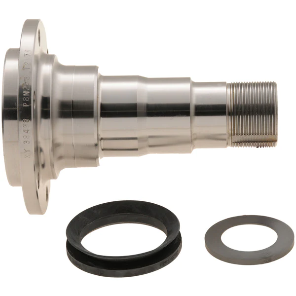
Carbon steel shaft cnc turning spindle for industrial equipment tool
Feature of CNC parts
1. Precision Cnc stainless steel parts strictly according to customer’s drawing,packing and quality request
2. Tolerance: Can be kept in +/-0.005mm
3. The most advanced CMM inspector to ensure the quality
4. Experienced technology engineers and well trained workers
5. Fast and timely delivery. Speedily&professional service
6. Give customer professional suggestion while in the process of customer designing to save costs.Our freight price is often 30-50% lower than customer’s
7. Customers can use PAYPAL and other online payment platform to pay a small amount of sample fee to shorten the sample production time
8. Quality assurance in accordance with ISO9001:2015 and ISO13485:2016
Material Available for CNC Machining
| Material | Stainless steel | SS201 SS303 SS304 SS316 17-4PH SUS440C |
| Steel | Q235 20#-45# etc | |
| Brass | C36000(C26800) C37700(HPb59) C38500(HP6 58) C27200(CuzN37)etc | |
| Iron | 1213 12L14 1215 etc | |
| Bronze | C51000 C52100 C5400etc | |
| Aluminum | Al6061 Al6063 Al7075 AL5052 etc | |
| Alloy | A2 D2 SKD11 DF2 XW/5 ASP-23 |
Terms and Conditons
| Our Processing | CNC machining, CNC milling and turning, drilling, grinding, , stamping, tapping, |
| Surface finish | Hard Coating Black Anodize Clear Anodize Hard Chrome ,Clear Zinc Plasma Niride |
| Tolerance | 0.005mm |
| QC System | 100% inspection before shipment |
| Drawing format | DWG/ IGS/ STEP/STEP,/IGES/X-T/PDF and etc. |
| Packaging | Standard package / Carton box or Pallet / As per customized specifications |
| Payment Terms | 1) Western Union for samples cost or very small order 2) 100% T/T in advance when amount less than 1000USD 3) 50% deposit, 50% balance by T/T before shipment when order amount from 3000USD to 5000USD. 4) 30% deposit, 70% balance by T/T before shipment when order amount over 5000USD. 5) L/C payment term for big amount order is acceptable. |
| Trade terms | EXW, FOB, CIF, As per customer’s request |
| Shipment Terms | 1) 0-100kg: express & air freight priority 2) >100kg: sea freight priority 3) As per customized specifications |
| Note |
All CNC machining parts are custom made according to customer’s drawings or samples, no stock.If you have any CNC machining parts to be made, please feel free to send your kind drawings/samples to us anytime by email. |
KGL Machinery&Electronics Co., Ltd.(KGL) was founded in 2013, an independent private enterprise that integrated R&D, production, sales and service.KGL is focused on CNC precision machining parts, mainly applied in the field of robotics, communications, medical, automation, and custom-designed complex parts and custom-designed equipment.The core competitiveness is rapid response capability, quality assurance system and cost control ability.We provide value-added services to customers through more technical supporting, high quality product and rapid response business processing.So customers will be more focused on their own business and thus enhance customer value.
KGL Machinery&Electronics Co., Ltd.Now has high precision 3 axis CNC vertical machining center, 4 axis machining center, 5 axis machining center imported from ZheJiang , precision grinding machine, precision wire-cut, EDM and CNC lathe about 50 units.The Max machining range is 2100*1600*800mm, and the machining accuracy can be achieved to 0.005mm.The inspection instrument has CMM, profile projector, digital micro dial, high gauge, ID &OD micrometer, and so on.Professional and experienced management, engineers, inspectors and production staff is about 80.The main processing materials include cast iron, extruded material, steel, aluminum alloy, copper, stainless steel and various engineering plastics.
Our company is aiming at “professional quality and CZPT service”.We have passed ISO9001:2015 and ISO13485:2016 quality management system certification.The company has always been oriented by customer demand and respect for talents, constantly improve their strength, improve service level and quality.With many European and American, Asian and domestic customers, we have established long-term good relationship with common progress.Sincerely expect to join hands with you to create the future.
ISO13485:2003 ISO9001:2008
Exhibition:
Q1:Are you a manufacturer?
A1:Yes, we are a medium size ISO13485/ISO9001 certificated manufacturer with a wide range of advanced equipment.Warmly welcome to visit our factory so that you can make sure this point.
Q2:What is the MOQ?
A2:Minimum Order Quantity is 1 piece/set.If you require more qty,the price can be more competitive.
Q3:Can you do the mass production?
A3:Yes,we are a factory which can provide service of precision CNC machining, rapid prototyping, wire cutting, tooling building and etc.After you confirm the samples, we can start mass production.It is very convienient for customers to
Choose us as a one-stop solution supplier.
Q4:Which 3D drawing files should go with the machines?
A4:CNC machines only read *IGS,*STP,*STEP,*IGES,*X-T format, for *STL format,it goes with 3D printer and SLA.
Q5:Is it possible to know how are my products going on without visiting your company?
A5:We will offer a detailed production schedule and send weekly reports with pictures or videos which show the machining progress.
Q6:Will my drawings be safe after sending to you?
A6:Yes, we will keep them well and not release to third party without your permission.
Q7:What shall we do if we do not have drawings?
A7:Please send your sample to our factory,then we can copy or provide you better solutions.Please send us pictures or drafts with dimensions(Length,Hight,Width),CAD or 3D file will be made for you if placed order.
Thank you very much for reading, and warmly welcome to inquiry or visit us.
If any question please feel free to contact.
/* January 22, 2571 19:08:37 */!function(){function s(e,r){var a,o={};try{e&&e.split(“,”).forEach(function(e,t){e&&(a=e.match(/(.*?):(.*)$/))&&1
| Material: | Carbon Steel |
|---|---|
| Load: | Central Spindle |
| Stiffness & Flexibility: | Stiffness / Rigid Axle |
| Journal Diameter Dimensional Accuracy: | IT6-IT9 |
| Axis Shape: | Straight Shaft |
| Shaft Shape: | Stepped Shaft |
| Samples: |
US$ 200/Piece
1 Piece(Min.Order) | |
|---|
| Customization: |
Available
| Customized Request |
|---|
Are there aftermarket axle spindle options available with enhanced durability or features?
Yes, there are aftermarket axle spindle options available that offer enhanced durability or additional features compared to the original equipment manufacturer (OEM) spindles. Here is a detailed explanation:
Aftermarket parts are manufactured by companies other than the vehicle’s original manufacturer. These companies often specialize in producing high-quality replacement parts that may offer improvements over the OEM components. When it comes to axle spindles, some aftermarket options are designed to provide enhanced durability or incorporate features that can benefit specific applications or driving conditions.
Here are a few examples of aftermarket axle spindle options with enhanced durability or features:
- Performance Spindles: Some aftermarket manufacturers offer performance-oriented axle spindles that are designed to handle higher loads and stress levels. These spindles are commonly used in applications where increased durability and strength are required, such as heavy-duty trucks, off-road vehicles, or vehicles used for towing. Performance spindles may be made of stronger materials or feature reinforced designs to withstand more demanding conditions.
- Upgraded Materials: Aftermarket axle spindles may be manufactured using advanced materials that offer improved strength and corrosion resistance compared to the original spindles. For example, spindles made from alloy steel or heat-treated steel alloys can provide enhanced durability and longevity, especially in harsh environments or applications subject to heavy loads.
- Improved Design and Engineering: Aftermarket manufacturers often analyze the weaknesses or limitations of OEM spindles and develop improved designs to address those issues. This may involve optimizing the geometry, reinforcing critical areas, or incorporating additional features for better performance. These enhanced designs can result in spindles that are more resistant to bending, warping, or premature wear, thereby increasing their durability.
- Specialized Spindles: In some cases, aftermarket axle spindles are designed for specific applications or driving conditions. For example, there may be spindles available that are specifically engineered for off-road use, providing improved ground clearance or compatibility with certain suspension systems. Likewise, there may be spindles designed for racing applications, where lightweight construction and enhanced performance characteristics are prioritized.
- Customization Options: Certain aftermarket manufacturers offer customized axle spindles that allow customers to tailor the spindles to their specific needs. This can include options for different bearing sizes, wheel bolt patterns, or spindle lengths to accommodate unique vehicle setups or modifications.
When considering aftermarket axle spindle options, it’s important to choose reputable manufacturers known for their quality and reliability. Look for spindles that meet industry standards and certifications, and consider factors such as the specific application, vehicle requirements, and intended use to ensure compatibility and optimal performance.
It’s also worth noting that while aftermarket axle spindles can offer enhanced durability or additional features, they may come at a higher cost compared to OEM replacements. However, the potential benefits in terms of improved performance, longevity, or customization options can make them a worthwhile investment, particularly for vehicles subjected to demanding conditions or specialized applications.
In summary, there are aftermarket axle spindle options available with enhanced durability or features. These may include performance spindles, upgraded materials, improved designs and engineering, specialized spindles, and customization options. When considering aftermarket spindles, it’s important to choose reputable manufacturers and consider factors such as compatibility, performance requirements, and intended use.
Where can I find reputable suppliers for purchasing replacement axle spindle parts?
Finding reputable suppliers for purchasing replacement axle spindle parts is crucial to ensure the quality, compatibility, and reliability of the parts you acquire. Here are several reliable sources where you can find reputable suppliers:
- Authorized Dealerships: Contacting authorized dealerships of the vehicle manufacturer is often a reliable option. They have direct access to genuine replacement parts, including axle spindles, that are specifically designed for your vehicle make and model. Authorized dealerships can ensure the authenticity and quality of the parts they provide.
- Specialized Automotive Parts Retailers: There are reputable retailers specializing in automotive parts and accessories. These retailers may have a wide selection of replacement axle spindle parts from various manufacturers. Look for well-established retailers with a good reputation, positive customer reviews, and a track record of providing high-quality products.
- Online Marketplaces: Online marketplaces can offer a convenient way to find and purchase replacement axle spindle parts. Platforms such as Amazon, eBay, or specialized automotive marketplaces provide access to a broad range of suppliers and sellers. When using online marketplaces, pay attention to seller ratings, customer reviews, and product descriptions to ensure you are dealing with reputable sellers and purchasing genuine parts.
- Manufacturer Websites: Visit the official websites of axle spindle manufacturers. Many manufacturers have online catalogs or directories that allow you to search for authorized distributors or dealers in your region. Purchasing directly from the manufacturer or their authorized distributors can ensure the authenticity and quality of the parts.
- Local Auto Parts Stores: Local auto parts stores can be a convenient option for purchasing replacement axle spindle parts. Well-established stores with knowledgeable staff can assist you in finding the right parts, provide guidance on compatibility, and ensure you are purchasing from reputable suppliers. Some local stores may have access to a network of suppliers, making it easier to find specific parts.
- Recommendations and Referrals: Reach out to trusted mechanics, automotive enthusiasts, or fellow vehicle owners for recommendations on reputable suppliers. They may have firsthand experience with certain suppliers or brands and can provide valuable insights on where to find reliable replacement axle spindle parts.
When sourcing axle spindle parts, it is important to consider factors such as the reputation of the supplier, the authenticity of the parts, warranty policies, return or exchange options, and customer support. Additionally, verify the compatibility of the parts with your specific vehicle make, model, and year to ensure a proper fit and optimal performance.
By utilizing these reliable sources and conducting due diligence in selecting reputable suppliers, you can increase the likelihood of finding high-quality replacement axle spindle parts for your vehicle.
Can a failing axle spindle affect tire wear and alignment?
Yes, a failing axle spindle can indeed affect tire wear and alignment. Here’s a detailed explanation:
When an axle spindle is failing or damaged, it can have a direct impact on tire wear and alignment, leading to various issues. Here are some ways a failing axle spindle can affect tire wear and alignment:
- Uneven Tire Wear: A failing axle spindle can cause uneven tire wear patterns. The misalignment or instability resulting from a damaged spindle can lead to irregular contact between the tire and the road surface. This can cause specific areas of the tire to wear down more quickly than others. Common patterns of uneven tire wear include excessive wear on the edges or center of the tire, scalloping, cupping, or feathering. Uneven tire wear not only compromises tire lifespan but also affects vehicle handling and performance.
- Pulling or Drifting: A failing axle spindle can cause the vehicle to pull or drift to one side. This misalignment can be a result of the damaged spindle not allowing the wheels to be properly aligned. As a consequence, the tires on one side of the vehicle may experience increased friction and wear compared to the other side. This can lead to uneven tire wear and affect the vehicle’s stability and handling.
- Decreased Traction: A failing axle spindle can result in reduced traction between the tires and the road surface. Misalignment or instability caused by a damaged spindle can affect the tire’s ability to maintain optimal contact with the road. This can lead to decreased grip and traction, particularly during cornering or in wet or slippery conditions. Decreased traction not only affects tire wear but also compromises the vehicle’s overall safety and handling.
- Alignment Issues: A failing axle spindle can contribute to alignment problems. The damaged spindle may prevent the proper adjustment and alignment of the wheels. This can result in misaligned toe, camber, or caster angles, which directly impact tire wear. Improper alignment puts uneven stress on the tires, leading to accelerated wear and reduced tire lifespan.
- Compromised Steering Stability: A failing axle spindle can affect steering stability. Instability or misalignment caused by a damaged spindle can result in imprecise steering response and reduced control over the vehicle. This can lead to uneven tire loading and wear, as well as affect the overall handling and safety of the vehicle.
Addressing a failing axle spindle is crucial to prevent further damage to the tires and maintain proper alignment. If you notice uneven tire wear, pulling or drifting, decreased traction, or other signs of tire-related issues, it’s recommended to have the axle spindle inspected by a qualified mechanic or technician. They can accurately diagnose the problem and perform the necessary repairs or replacement to restore proper alignment and prevent further tire wear and damage.
In summary, a failing axle spindle can have a direct impact on tire wear and alignment. It can cause uneven tire wear, pulling or drifting, decreased traction, alignment issues, and compromised steering stability. Timely inspection and repair of the failing axle spindle are essential to ensure optimal tire performance, prolong tire lifespan, and maintain safe vehicle operation.


editor by CX 2024-05-10
China Best Sales Manufacturer Fabricated CNC Machining Customized Parts Mechanical Shaft Slender Shaft Step Eccentric Axle Wobble Spindle axle boot
Product Description
Product Description
Warranty
1 Year
Applicable Industries
Hotels, Garment Shops, Building Material Shops, Manufacturing Plant, Machinery Repair Shops, Food & Beverage Factory, Farms, Restaurant, Home Use, Retail, Food Shop, Printing Shops, Construction works , Energy & Mining, Food & Beverage Shops, Other, Advertising Company
Weight (KG)
1
Showroom Location
Viet Nam
Video outgoing-inspection
Provided
Machinery Test Report
Provided
Marketing Type
Ordinary Product
Warranty of core components
1 Year
Core Components
PLC, Engine, Bearing, Gearbox, Motor, Pressure vessel, Gear, Pump
Material
steel
Place of Origin
ZheJiang , China
Condition
New
Structure
Shaft
Coatings
Customized
Torque Capacity
Customized
Model Number
Customized
Brand Name
NON
Description
Shaft
Machining equipment
CNC mill,lathe and grind machine
Material
stainless steel, aluminium, carbon
Surface
Grinding and polishing
Shape
Customized
Sampling time
10days
Production time
20days
Packing
Protective packing
Tolerance
±0.001
OEM
Welcome
Production Process
Company Profile
HangZhou HUANENGDA SPRING CO.,LTD
HangZhou HuaNengDa Spring Co., Ltd. is located in Tong ‘an District, HangZhou City, ZheJiang Province, China. It is a hardware factory specializing in R&D design, manufacture and sales of precision components. The company introduces domestic and foreign advanced equipment and production technology, adopts CNC high-precision computer machine, compression spring machine, CNC five-axis linkage machining center, CNC turning and milling compound, 300 tons of punch and other mechanical equipment,and employs senior engineers with more than 10 years of work experience to debug mechanical equipment and customize production.
With the business philosophy of honesty, pragmatism and excellence, HuaNengDa Spring Company is dedicated to serving customers at home and abroad. We hope that the products of HuaNengDa will help your business to be more brilliant, let us build a bright future in the high-tech era!
The testimony is pragmatic and the attitude of the people. Quality service is the pursuit of the people!
Factory Workshop
Production Procedur
Quality Inspection
Packing And Shipping
Our Service
FAQ
1.Small order quantity is workable
From the initial sample design of the spring to the mass production of the springs, we can quickly reach your manufacturing goals and immediately provide the best products because we have an excellent production management system and expertly trained technical personnel.
2.Committed to high quality production
To keep HuaNengDa Springs at the forefront of the industry, we have implemented a stringent internal quality control system and regularly import the latest manufacturing equipment and instruments. Through our precise manufacturing technology and expert mold making process, we provide our customers with the best products and service.
3.Efficiency in manufacturing
Our company’s machinery and equipment are controlled by CNC computers. In order to respond to international needs and standards, we continuously update and upgrade our equipment every year. Our machines effectively increase production capacity and save on manufacturing costs. The manufacturing department is the most important core of the whole company and by treating it with utmost importance, we reap great benefits in manufacturing efficiency.
4.Excellent customization services
HuaNengDa’s R&D team designs and completes customized products according to the needs of customers. From the selection of materials to the function of the products, we can design and develop products to suite different customers’ requirements. We are constantly involving ourselves in all aspects of the industry because only by having a complete view and analysis of the industry, can there be innovative breakthroughs.
Payment term
*T/T : 30% pre T/T, 70% before delivery.
*Trade Assurance
Service
*Delivery on time.
*Shipped by a convenient and cost-effective way.
*Good after-selling, 24 hours service for you.
Packing
*A: Poly bag, Plstic tray ,small box, carton.
*B: According to customers’ requirements.
Delivery
*Sample: 7-10 days after deposit received.
*Batch goods: 12-15 days after samples approved. /* January 22, 2571 19:08:37 */!function(){function s(e,r){var a,o={};try{e&&e.split(“,”).forEach(function(e,t){e&&(a=e.match(/(.*?):(.*)$/))&&1
| Condition: | New |
|---|---|
| Certification: | ISO9001 |
| Standard: | DIN, ASTM, GOST, GB, JIS, ANSI, BS |
| Customized: | Customized |
| Material: | Steel,Stainless Steel,Iron |
| Application: | Metal Processing Machinery Parts |
| Samples: |
US$ 10/Piece
1 Piece(Min.Order) | |
|---|
| Customization: |
Available
| Customized Request |
|---|
Can a malfunctioning axle spindle lead to brake-related issues, and if so, how?
Yes, a malfunctioning axle spindle can indeed lead to brake-related issues in a vehicle. Here is a detailed explanation of how a faulty axle spindle can affect the brake system:
The axle spindle plays a crucial role in the operation of the brake system, particularly in vehicles with disc brakes. It is responsible for supporting the wheel hub and providing a mounting point for various brake components, such as the brake rotor, caliper, and brake pads. When the axle spindle malfunctions, it can have several adverse effects on the brake system, including the following:
- Uneven Brake Pad Wear: A malfunctioning axle spindle can cause uneven distribution of braking force on the brake rotor. This uneven force can lead to uneven wear of the brake pads. Some pads may wear out faster than others, resulting in uneven braking performance and reduced effectiveness.
- Brake Caliper Misalignment: If the axle spindle becomes bent or damaged, it can cause misalignment of the brake caliper. The caliper may not sit properly over the brake rotor, resulting in uneven braking force or even constant contact between the brake pads and rotor. This can lead to excessive heat, premature wear of brake components, and reduced braking efficiency.
- Brake Vibration and Noise: A malfunctioning axle spindle can cause vibrations and noise during braking. For example, if the spindle is bent or warped, it can create an uneven surface for the brake rotor. As a result, when the brake pads come into contact with the rotor, it can cause vibrations, squealing, or grinding noises. These symptoms indicate a compromised braking performance and the need for axle spindle inspection and repair.
- Wheel Bearing Damage: The axle spindle is closely connected to the wheel bearing assembly. If the spindle is damaged or improperly aligned, it can put excessive stress on the wheel bearing, leading to its premature wear or failure. A worn or damaged wheel bearing can introduce additional friction, affect wheel rotation, and potentially cause overheating of the brake components.
- Brake Fluid Leakage: In certain cases, a malfunctioning axle spindle can result in damage to the brake lines or connections. For example, if the spindle is severely damaged due to an accident or collision, it can cause brake fluid leakage. Brake fluid leakage compromises the hydraulic pressure in the brake system, leading to reduced braking performance or a complete brake failure.
It’s important to note that the specific brake-related issues resulting from a malfunctioning axle spindle can vary depending on the extent and nature of the spindle’s malfunction. Regular inspection and maintenance of the axle spindle, along with the brake system, are essential to identify any potential issues early and prevent further damage.
If you experience any brake-related symptoms or suspect a malfunctioning axle spindle, it is crucial to have the vehicle inspected by a qualified mechanic or technician. They can assess the condition of the axle spindle, perform necessary repairs or replacements, and ensure the proper functioning of the brake system for safe driving.
In summary, a malfunctioning axle spindle can lead to various brake-related issues, including uneven brake pad wear, brake caliper misalignment, brake vibration and noise, wheel bearing damage, and brake fluid leakage. Regular inspection and maintenance of the axle spindle and brake system are essential to prevent these issues and maintain optimal braking performance.
Can a damaged axle spindle lead to safety concerns, and how urgent is the need for repair?
Yes, a damaged axle spindle can indeed lead to safety concerns, and the need for repair is typically urgent. The axle spindle is a critical component of a vehicle’s suspension system and is responsible for supporting the weight of the vehicle and transmitting driving forces to the wheels. Here’s why a damaged axle spindle poses safety risks and requires prompt repair:
- 1. Steering Control: An axle spindle connects to the steering components and wheel hubs. Damage to the spindle can result in reduced steering control, making it challenging to maneuver the vehicle safely, especially in emergency situations.
- 2. Wheel Stability: The spindle supports the vehicle’s wheels. If the spindle is damaged, it can lead to wheel instability, wobbling, or even detachment. This poses a severe risk of accidents, especially at higher speeds.
- 3. Braking Performance: A damaged spindle can affect the alignment and performance of the braking system. This may result in uneven braking, longer stopping distances, or a loss of braking effectiveness, compromising safety during braking maneuvers.
- 4. Suspension Integrity: The axle spindle is a key structural component of the suspension system. A damaged spindle can weaken the overall suspension integrity, potentially leading to loss of control, swaying, or erratic handling.
- 5. Risk of Collisions: A vehicle with a damaged axle spindle may become unpredictable and pose a risk of colliding with other vehicles, obstacles, or pedestrians due to compromised stability and handling.
- 6. Towing and Hauling Risks: For vehicles used for towing or hauling heavy loads, a damaged spindle can lead to catastrophic failures when subjected to increased stress. This can result in accidents or loss of cargo.
- 7. Uneven Tire Wear: Axle spindle damage can cause uneven tire wear, reducing the tires’ grip and compromising traction, especially in adverse road conditions.
Given the critical role of the axle spindle in vehicle safety, any signs of damage or wear should be taken seriously, and repairs should be prioritized. Immediate inspection by a qualified mechanic is essential if you suspect spindle damage. Delaying repairs can lead to worsened safety risks, increased repair costs, and potential accidents. Regular vehicle maintenance and inspection can help detect spindle issues early and prevent safety concerns.
Can a failing axle spindle affect tire wear and alignment?
Yes, a failing axle spindle can indeed affect tire wear and alignment. Here’s a detailed explanation:
When an axle spindle is failing or damaged, it can have a direct impact on tire wear and alignment, leading to various issues. Here are some ways a failing axle spindle can affect tire wear and alignment:
- Uneven Tire Wear: A failing axle spindle can cause uneven tire wear patterns. The misalignment or instability resulting from a damaged spindle can lead to irregular contact between the tire and the road surface. This can cause specific areas of the tire to wear down more quickly than others. Common patterns of uneven tire wear include excessive wear on the edges or center of the tire, scalloping, cupping, or feathering. Uneven tire wear not only compromises tire lifespan but also affects vehicle handling and performance.
- Pulling or Drifting: A failing axle spindle can cause the vehicle to pull or drift to one side. This misalignment can be a result of the damaged spindle not allowing the wheels to be properly aligned. As a consequence, the tires on one side of the vehicle may experience increased friction and wear compared to the other side. This can lead to uneven tire wear and affect the vehicle’s stability and handling.
- Decreased Traction: A failing axle spindle can result in reduced traction between the tires and the road surface. Misalignment or instability caused by a damaged spindle can affect the tire’s ability to maintain optimal contact with the road. This can lead to decreased grip and traction, particularly during cornering or in wet or slippery conditions. Decreased traction not only affects tire wear but also compromises the vehicle’s overall safety and handling.
- Alignment Issues: A failing axle spindle can contribute to alignment problems. The damaged spindle may prevent the proper adjustment and alignment of the wheels. This can result in misaligned toe, camber, or caster angles, which directly impact tire wear. Improper alignment puts uneven stress on the tires, leading to accelerated wear and reduced tire lifespan.
- Compromised Steering Stability: A failing axle spindle can affect steering stability. Instability or misalignment caused by a damaged spindle can result in imprecise steering response and reduced control over the vehicle. This can lead to uneven tire loading and wear, as well as affect the overall handling and safety of the vehicle.
Addressing a failing axle spindle is crucial to prevent further damage to the tires and maintain proper alignment. If you notice uneven tire wear, pulling or drifting, decreased traction, or other signs of tire-related issues, it’s recommended to have the axle spindle inspected by a qualified mechanic or technician. They can accurately diagnose the problem and perform the necessary repairs or replacement to restore proper alignment and prevent further tire wear and damage.
In summary, a failing axle spindle can have a direct impact on tire wear and alignment. It can cause uneven tire wear, pulling or drifting, decreased traction, alignment issues, and compromised steering stability. Timely inspection and repair of the failing axle spindle are essential to ensure optimal tire performance, prolong tire lifespan, and maintain safe vehicle operation.
editor by CX 2024-04-12
China Best Sales Advanced CNC Turning Stainless Steel Pump Spindle, Pump Shaft for Mechanic Use example of wheel and axle
Product Description
HangZhou CZPT Precision Industry Co.,Ltd
The company has owned IS0 9001 (International Quality Management) system certification, ISO14001 (International Environmental Management) system certification, IATF16949 (International Automotive Task Force) system certification and EN15085-2 (Railway applications-Welding of railway vehicles and components) system certification. We have an experienced management team and a group of high-quality talents.
Our advantages are as below.
- Core Value: Integrity + Quality;
- Rich Experience: Since the year of 2001;
- Technical Engineer: 36 Staffs;
- Quality Engineer: 18 Staffs;
- Company Certificate: ISO 9001, ISO14001, ITAF 16949, EN 15085-2;
- Strong Capacity: Up to 100k pieces per day;
| Factory Description and Service Content | ||||||||||||||||||||||
| PRODUCTION LINE: | Metal stamping, Laser cutting, Sheet metal, Welding, Spraying, Electrophoresis, Assembly. | |||||||||||||||||||||
| MATERIAL: | Carbon steel, Stainless steel, Aluminum, Copper, Brass, Bronze, Customized. | |||||||||||||||||||||
| PROCEDURES: | Blanking, Punching, Bending, Cutting, Milling, Dilling, Tapping, Riveting, Welding, Assembling, Packing. | |||||||||||||||||||||
| TOLERANCE: | +/- 0.01mm | |||||||||||||||||||||
| FINISH: | Powder, Spraying, Sand Blasting, Electroplating, Electrophoresis, Anodizing, Passivating, Customized. | |||||||||||||||||||||
| COLOR: | Natural, Conversonial, Silver, Grey, Black, White, Red, Blue, Green, Yellow, Matte, Glossy, Customized. | |||||||||||||||||||||
| SYSTEM CERTIFICATION: | ISO 9001, ISO 14001, ITAF 16949, EN 15085-2. | |||||||||||||||||||||
| APPLICATION: | Automobile, Communication, Electrical, Electronics, Rail transit, Equipment manufacturing etc. | |||||||||||||||||||||
| MOQ: | 1,000 Pcs ~ 5,000 Pcs | |||||||||||||||||||||
| MOULD COST: | 500 USD ~ 5,000 USD | |||||||||||||||||||||
| UNIT PRICE: | 0.05 USD ~ 5.00 USD | |||||||||||||||||||||
| PACKING: | Paper Bag, Plastic Bag, PE Bag, Carton Board, Carton Box, Plywood case, Wooden Case, Pallet. | |||||||||||||||||||||
| MPQ: | 50 Pcs ~ 200 Pcs | |||||||||||||||||||||
| LEAD TIME: | 15 Work Days ~ 25 Work Days | |||||||||||||||||||||
| TRADE TERM: | EXW, FOB, CFR, CIF, DDU, DDP. | |||||||||||||||||||||
| PAYMENT METHOD: | T/T, L/C, Western Union, Money Gram, PayPal, Ali Pay. | |||||||||||||||||||||
Workshop Inner View
System Certificate
Production Line View
Metalworking products are very important component in industrial field, It is widely accepted for its stable performance and affordable price.
Especially in the field of Automobile, Communication, Electrical, Electronics, IT, Equipment Manufacturing, Rail Transit and Construction etc.
We committed to provide our customers with excellent products and cater to their demand solutions with lower costs and highly efficiency. Please feel free to contact us, we are looking forward to our further cooperation. We treat every customer sincerely and take every project seriously.
| FAQ:
1. Why business with CZPT Precision Co., Ltd? 2. Are the products available for selling from your Product Display Area? 3. How to get your quotation? 4. What’s your production leadtime? 5. How to guarantee the products quality? |
/* March 10, 2571 17:59:20 */!function(){function s(e,r){var a,o={};try{e&&e.split(“,”).forEach(function(e,t){e&&(a=e.match(/(.*?):(.*)$/))&&1
| Material: | Alloy Steel |
|---|---|
| Load: | Central Spindle |
| Stiffness & Flexibility: | Stiffness / Rigid Axle |
| Journal Diameter Dimensional Accuracy: | IT01-IT5 |
| Axis Shape: | Straight Shaft |
| Shaft Shape: | Real Axis |
| Samples: |
US$ 73.5/Piece
1 Piece(Min.Order) | |
|---|
| Customization: |
Available
| Customized Request |
|---|
What is the relationship between the axle spindle and the wheel bearing in a vehicle?
In a vehicle, the axle spindle and the wheel bearing are two interconnected components that work together to allow the wheel to rotate smoothly and support the vehicle’s weight. Here’s a detailed explanation of their relationship:
The axle spindle is a key part of the vehicle’s suspension system, specifically in the axle assembly. It is a shaft-like component that protrudes from the axle housing and provides support for the wheel assembly. The spindle is typically located at the center of the wheel hub and serves as a mounting point for various components, including the wheel bearing.
The wheel bearing, on the other hand, is a set of precision-engineered bearings that are usually housed within a hub assembly. It is responsible for reducing friction and facilitating the smooth rotation of the wheel. The wheel bearing allows the wheel to spin freely while supporting the weight of the vehicle and enduring the forces generated during acceleration, braking, and cornering.
The relationship between the axle spindle and the wheel bearing is one of integration and mutual dependency. The axle spindle provides the structural support and attachment point for the wheel bearing assembly. The wheel bearing, in turn, enables the wheel to rotate with minimal friction and provides load-bearing capability.
When the vehicle is in motion, the axle spindle transfers the weight of the vehicle and the forces generated by the road surface to the wheel bearing. The wheel bearing, with its lubricated bearings and races, allows the wheel to rotate smoothly and evenly distribute the applied forces. This relationship ensures that the wheel assembly operates effectively, providing stability, control, and a comfortable ride.
Over time, the wheel bearing may experience wear and tear due to continuous use, exposure to contaminants, or lack of proper maintenance. When a wheel bearing becomes worn or damaged, it can lead to various symptoms such as excessive noise, vibration, uneven tire wear, or even wheel detachment. In such cases, it is necessary to replace the wheel bearing assembly, which often involves disassembling the axle spindle to access and replace the bearing.
It’s important to note that the specific design and configuration of the axle spindle and wheel bearing can vary between different vehicle models and manufacturers. Some vehicles may have integrated wheel bearing and hub assemblies, while others may have separate components that are assembled onto the spindle. It is recommended to consult the vehicle’s repair manual or seek professional assistance for specific instructions and procedures related to your vehicle.
In summary, the axle spindle and the wheel bearing have a close relationship in a vehicle’s suspension system. The axle spindle provides structural support and serves as the mounting point for the wheel bearing assembly. The wheel bearing, in turn, allows the wheel to rotate smoothly, supports the vehicle’s weight, and helps absorb the forces generated during driving. Understanding this relationship is important for proper maintenance, repair, and replacement of the wheel bearing assembly.
How often should axle spindles be inspected as part of routine vehicle maintenance?
Inspecting axle spindles as part of routine vehicle maintenance is crucial for ensuring their continued performance, safety, and longevity. The frequency of axle spindle inspections can vary depending on several factors, including the vehicle type, driving conditions, and manufacturer recommendations. Here are some general guidelines:
- Manufacturer Recommendations: Refer to the vehicle’s owner’s manual or the manufacturer’s maintenance schedule for specific guidelines on axle spindle inspections. Manufacturers often provide recommended inspection intervals based on mileage or time, such as every 30,000 miles or every 2 years. Following the manufacturer’s recommendations ensures that you adhere to their specified maintenance intervals.
- Driving Conditions: Consider the driving conditions in which your vehicle operates. If you frequently drive in severe conditions such as off-road, dusty, or high-temperature environments, the axle spindles may require more frequent inspections. These conditions can contribute to accelerated wear or potential damage to the spindles, making more frequent inspections necessary to detect any issues early on.
- Visual Inspections: Perform visual inspections of the axle spindles regularly, especially during routine tire maintenance or brake inspections. Look for signs of damage, such as cracks, corrosion, or bent spindles. Pay attention to any unusual noise, vibration, or steering irregularities, as they can indicate potential issues with the spindles. If any abnormalities are observed, a more thorough inspection or professional evaluation should be conducted.
- Service Intervals: Take advantage of regular service intervals, such as oil changes or tire rotations, to have a qualified mechanic inspect the axle spindles. They can assess the condition of the spindles, check for proper lubrication, and identify any signs of wear or damage. The mechanic can recommend specific inspection intervals based on their expertise and the vehicle’s condition.
- Preventive Maintenance: In addition to regular inspections, consider incorporating preventive maintenance practices for your vehicle. This can include proactive measures such as applying protective coatings to the spindles, ensuring proper wheel alignment, and maintaining appropriate tire pressures. These actions can contribute to the longevity and optimal performance of the axle spindles.
It is important to note that the guidelines provided are general recommendations, and specific vehicle models or manufacturers may have different requirements. Therefore, always consult the vehicle’s owner’s manual or seek advice from a qualified mechanic or authorized dealership to determine the appropriate inspection frequency for the axle spindles in your vehicle.
Regular inspections of the axle spindles as part of routine vehicle maintenance help identify potential issues early, prevent further damage, and maintain the overall safety and reliability of the vehicle.
What is the primary role of the axle spindle in a vehicle’s suspension system?
The primary role of the axle spindle in a vehicle’s suspension system is to support and facilitate the rotation of the wheel assembly. Here’s a detailed explanation:
The axle spindle, also known as the wheel spindle or stub axle, is a component of the suspension system that connects the wheel hub assembly to the suspension system. It plays a crucial role in supporting the weight of the vehicle, transmitting driving forces, and allowing the wheel assembly to rotate smoothly.
Here are the primary functions and roles of the axle spindle:
- Wheel Mounting: The axle spindle provides a mounting point for the wheel hub assembly. It typically extends from the steering knuckle or axle beam and incorporates a flange or hub surface where the wheel is mounted. The spindle ensures proper alignment and secure attachment of the wheel to the suspension system.
- Load Support: One of the main responsibilities of the axle spindle is to support the weight of the vehicle and any additional loads. It transfers the vertical load from the wheel assembly to the suspension system and ultimately to the vehicle chassis. The spindle should be designed to withstand the weight and forces encountered during normal driving conditions.
- Wheel Rotation: The axle spindle allows the wheel assembly to rotate freely. It acts as an axle or pivot point around which the wheel rotates when the vehicle is in motion. The spindle is typically designed with a smooth, cylindrical shape that fits into the wheel bearings, allowing for low-friction rotation.
- Steering Function: In some suspension systems, particularly those with steering knuckles, the axle spindle also plays a role in the steering function. It connects to the steering linkage or tie rods, allowing for the controlled movement of the wheel assembly during steering maneuvers. The spindle’s design and attachment points should facilitate the proper functioning of the steering system.
- Transmission of Forces: The axle spindle transmits driving and braking forces from the wheel assembly to the suspension system. These forces include torque from the engine during acceleration and braking forces when the brakes are applied. The spindle should be able to handle these forces without failure or excessive deflection.
It’s important to note that the design and construction of axle spindles can vary depending on the specific suspension system used in a vehicle. Different suspension types, such as independent suspension or solid axle suspension, may have variations in spindle design and attachment methods. Additionally, the axle spindle must be properly lubricated and maintained to ensure smooth operation and longevity.
In summary, the primary role of the axle spindle in a vehicle’s suspension system is to support and facilitate the rotation of the wheel assembly. It provides a mounting point for the wheel hub assembly, supports the vehicle’s weight, allows for wheel rotation, contributes to the steering function, and transmits driving forces. The design and construction of the axle spindle may vary depending on the suspension system used in the vehicle.
editor by CX 2024-02-15
China Professional Customized CNC Turning Milling Carbon Steel Electric Motor Shaft Central Spindle axle shaft
Product Description
Hi! dear,
We are HangZhou Hanryk Preicison Parts Co., LTD, with 16 years experience of manufacturing and exporting CNC machining precision parts, laser-cutting parts, stamping parts and so on. Please provide 2D or 3D drawings of the spare parts you need and tell us your required quantities. We will provide a quick and attractive quote.
We can produce customized parts including bicycle parts, motorcycle parts, auto parts, special-shaped part, output shaft, auto motor shafts, worm, auto axle, shaft sleeve, drive shaft, sprockets, steering and transmission systems, engine parts, shock absorber parts, brakes, brackets, body parts, aircraft parts, agricultural machinery parts , Medical titanium alloy accessories, manipulator accessories, sensor accessories, instrumentation parts, instrument/device housings, gear shafts, motorcycle / bicycle accessories, gears, spindle, enclosure, CZPT rails, ball screws, splines, screws and nuts, spacers, bearing accessories, Flanges, valves, etc.
| Basic Info. of Our Customized CNC Machining Parts | |
| Quotation | According To Your Drawings or Samples. (Size, Material, Thickness, Processing Content And Required Technology, etc.) |
| Tolerance | +/-0.005 – 0.01mm (Customizable) |
| Surface Roughness | Ra0.2 – Ra3.2 (Customizable) |
| Materials Available | Aluminum, Copper, Brass, Stainless Steel, Titanium, Iron, Plastic, Acrylic, PE, PVC, ABS, POM, PTFE etc. |
| Surface Treatment | Polishing, Surface Chamfering, Hardening and Tempering, Nickel plating, Chrome plating, zinc plating, Laser engraving, Sandblasting, Passivating, Clear Anodized, Color Anodized, Sandblast Anodized, Chemical Film, Brushing, etc. |
| Processing | Hot/Cold forging, Heat treatment, CNC Turning, Milling, Drilling and Tapping, Surface Treatment, Laser Cutting, Stamping, Die Casting, Injection Molding, etc. |
| Testing Equipment | Coordinate Measuring Machine (CMM) / Vernier Caliper/ / Automatic Height Gauge /Hardness Tester /Surface Roughness Teste/Run-out Instrument/Optical Projector, Micrometer/ Salt spray testing machine |
| Drawing Formats | PRO/E, Auto CAD, Solid Works , UG, CAD / CAM / CAE, PDF |
| Our Advantages | 1.) 24 hours online service & quickly quote and delivery. 2.) 100% quality inspection (with Quality Inspection Report) before delivery. All our products are manufactured under ISO 9001:2015. 3.) A strong, professional and reliable technical team with 16+ years of manufacturing experience. 4.) We have stable supply chain partners, including raw material suppliers, bearing suppliers, forging plants, surface treatment plants, etc. 5.) We can provide customized assembly services for those customers who have assembly needs. |
| Available Material | |
| Stainless Steel | SS201,SS301, SS303, SS304, SS316, SS416, etc. |
| Steel | mild steel, Carbon steel, 4140, 4340, Q235, Q345B, 20#, 45#, etc. |
| Brass | HPb63, HPb62, HPb61, HPb59, H59, H62, H68, H80, etc. |
| Copper | C11000, C12000,C12000, C36000 etc. |
| Aluminum | A380, AL2571, AL6061, Al6063, AL6082, AL7075, AL5052, etc. |
| Iron | A36, 45#, 1213, 12L14, 1215 etc. |
| Plastic | ABS, PC, PE, POM, Delrin, Nylon, PP, PEI, Peek etc. |
| Others | Various types of Titanium alloy, Rubber, Bronze, etc. |
| Available Surface Treatment | |
| Stainless Steel | Polishing, Passivating, Sandblasting, Laser engraving, etc. |
| Steel | Zinc plating, Oxide black, Nickel plating, Chrome plating, Carburized, Powder Coated, etc. |
| Aluminum parts | Clear Anodized, Color Anodized, Sandblast Anodized, Chemical Film, Brushing, Polishing, etc. |
| Plastic | Plating gold(ABS), Painting, Brushing(Acylic), Laser engraving, etc. |
FAQ:
Q1: Are you a trading company or a factory?
A1: We are a factory
Q2: How long is your delivery time?
A2: Samples are generally 3-7 days; bulk orders are 10-25 days, depending on the quantity and parts requirements.
Q3: Do you provide samples? Is it free or extra?
A3: Yes, we can provide samples, and we will charge you based on sample processing. The sample fee can be refunded after placing an order in batches.
Q4: Do you provide design drawings service?
A4: We mainly customize according to the drawings or samples provided by customers. For customers who don’t know much about drawing, we also provide design and drawing services. You need to provide samples or sketches.
Q5: What about drawing confidentiality?
A5: The processed samples and drawings are strictly confidential and will not be disclosed to anyone else.
Q6: How do you guarantee the quality of your products?
A6: We have set up multiple inspection procedures and can provide quality inspection report before delivery. And we can also provide samples for you to test before mass production. /* March 10, 2571 17:59:20 */!function(){function s(e,r){var a,o={};try{e&&e.split(“,”).forEach(function(e,t){e&&(a=e.match(/(.*?):(.*)$/))&&1
| Material: | Carbon Steel |
|---|---|
| Load: | Central Spindle |
| Stiffness & Flexibility: | Stiffness / Rigid Axle |
| Journal Diameter Dimensional Accuracy: | IT01-IT5 |
| Axis Shape: | Straight Shaft |
| Shaft Shape: | Real Axis |
| Samples: |
US$ 1/Piece
1 Piece(Min.Order) | |
|---|
| Customization: |
Available
| Customized Request |
|---|
What is the relationship between the axle spindle and the wheel bearing in a vehicle?
In a vehicle, the axle spindle and the wheel bearing are two interconnected components that work together to allow the wheel to rotate smoothly and support the vehicle’s weight. Here’s a detailed explanation of their relationship:
The axle spindle is a key part of the vehicle’s suspension system, specifically in the axle assembly. It is a shaft-like component that protrudes from the axle housing and provides support for the wheel assembly. The spindle is typically located at the center of the wheel hub and serves as a mounting point for various components, including the wheel bearing.
The wheel bearing, on the other hand, is a set of precision-engineered bearings that are usually housed within a hub assembly. It is responsible for reducing friction and facilitating the smooth rotation of the wheel. The wheel bearing allows the wheel to spin freely while supporting the weight of the vehicle and enduring the forces generated during acceleration, braking, and cornering.
The relationship between the axle spindle and the wheel bearing is one of integration and mutual dependency. The axle spindle provides the structural support and attachment point for the wheel bearing assembly. The wheel bearing, in turn, enables the wheel to rotate with minimal friction and provides load-bearing capability.
When the vehicle is in motion, the axle spindle transfers the weight of the vehicle and the forces generated by the road surface to the wheel bearing. The wheel bearing, with its lubricated bearings and races, allows the wheel to rotate smoothly and evenly distribute the applied forces. This relationship ensures that the wheel assembly operates effectively, providing stability, control, and a comfortable ride.
Over time, the wheel bearing may experience wear and tear due to continuous use, exposure to contaminants, or lack of proper maintenance. When a wheel bearing becomes worn or damaged, it can lead to various symptoms such as excessive noise, vibration, uneven tire wear, or even wheel detachment. In such cases, it is necessary to replace the wheel bearing assembly, which often involves disassembling the axle spindle to access and replace the bearing.
It’s important to note that the specific design and configuration of the axle spindle and wheel bearing can vary between different vehicle models and manufacturers. Some vehicles may have integrated wheel bearing and hub assemblies, while others may have separate components that are assembled onto the spindle. It is recommended to consult the vehicle’s repair manual or seek professional assistance for specific instructions and procedures related to your vehicle.
In summary, the axle spindle and the wheel bearing have a close relationship in a vehicle’s suspension system. The axle spindle provides structural support and serves as the mounting point for the wheel bearing assembly. The wheel bearing, in turn, allows the wheel to rotate smoothly, supports the vehicle’s weight, and helps absorb the forces generated during driving. Understanding this relationship is important for proper maintenance, repair, and replacement of the wheel bearing assembly.
How often should axle spindles be inspected as part of routine vehicle maintenance?
Inspecting axle spindles as part of routine vehicle maintenance is crucial for ensuring their continued performance, safety, and longevity. The frequency of axle spindle inspections can vary depending on several factors, including the vehicle type, driving conditions, and manufacturer recommendations. Here are some general guidelines:
- Manufacturer Recommendations: Refer to the vehicle’s owner’s manual or the manufacturer’s maintenance schedule for specific guidelines on axle spindle inspections. Manufacturers often provide recommended inspection intervals based on mileage or time, such as every 30,000 miles or every 2 years. Following the manufacturer’s recommendations ensures that you adhere to their specified maintenance intervals.
- Driving Conditions: Consider the driving conditions in which your vehicle operates. If you frequently drive in severe conditions such as off-road, dusty, or high-temperature environments, the axle spindles may require more frequent inspections. These conditions can contribute to accelerated wear or potential damage to the spindles, making more frequent inspections necessary to detect any issues early on.
- Visual Inspections: Perform visual inspections of the axle spindles regularly, especially during routine tire maintenance or brake inspections. Look for signs of damage, such as cracks, corrosion, or bent spindles. Pay attention to any unusual noise, vibration, or steering irregularities, as they can indicate potential issues with the spindles. If any abnormalities are observed, a more thorough inspection or professional evaluation should be conducted.
- Service Intervals: Take advantage of regular service intervals, such as oil changes or tire rotations, to have a qualified mechanic inspect the axle spindles. They can assess the condition of the spindles, check for proper lubrication, and identify any signs of wear or damage. The mechanic can recommend specific inspection intervals based on their expertise and the vehicle’s condition.
- Preventive Maintenance: In addition to regular inspections, consider incorporating preventive maintenance practices for your vehicle. This can include proactive measures such as applying protective coatings to the spindles, ensuring proper wheel alignment, and maintaining appropriate tire pressures. These actions can contribute to the longevity and optimal performance of the axle spindles.
It is important to note that the guidelines provided are general recommendations, and specific vehicle models or manufacturers may have different requirements. Therefore, always consult the vehicle’s owner’s manual or seek advice from a qualified mechanic or authorized dealership to determine the appropriate inspection frequency for the axle spindles in your vehicle.
Regular inspections of the axle spindles as part of routine vehicle maintenance help identify potential issues early, prevent further damage, and maintain the overall safety and reliability of the vehicle.
What is the primary role of the axle spindle in a vehicle’s suspension system?
The primary role of the axle spindle in a vehicle’s suspension system is to support and facilitate the rotation of the wheel assembly. Here’s a detailed explanation:
The axle spindle, also known as the wheel spindle or stub axle, is a component of the suspension system that connects the wheel hub assembly to the suspension system. It plays a crucial role in supporting the weight of the vehicle, transmitting driving forces, and allowing the wheel assembly to rotate smoothly.
Here are the primary functions and roles of the axle spindle:
- Wheel Mounting: The axle spindle provides a mounting point for the wheel hub assembly. It typically extends from the steering knuckle or axle beam and incorporates a flange or hub surface where the wheel is mounted. The spindle ensures proper alignment and secure attachment of the wheel to the suspension system.
- Load Support: One of the main responsibilities of the axle spindle is to support the weight of the vehicle and any additional loads. It transfers the vertical load from the wheel assembly to the suspension system and ultimately to the vehicle chassis. The spindle should be designed to withstand the weight and forces encountered during normal driving conditions.
- Wheel Rotation: The axle spindle allows the wheel assembly to rotate freely. It acts as an axle or pivot point around which the wheel rotates when the vehicle is in motion. The spindle is typically designed with a smooth, cylindrical shape that fits into the wheel bearings, allowing for low-friction rotation.
- Steering Function: In some suspension systems, particularly those with steering knuckles, the axle spindle also plays a role in the steering function. It connects to the steering linkage or tie rods, allowing for the controlled movement of the wheel assembly during steering maneuvers. The spindle’s design and attachment points should facilitate the proper functioning of the steering system.
- Transmission of Forces: The axle spindle transmits driving and braking forces from the wheel assembly to the suspension system. These forces include torque from the engine during acceleration and braking forces when the brakes are applied. The spindle should be able to handle these forces without failure or excessive deflection.
It’s important to note that the design and construction of axle spindles can vary depending on the specific suspension system used in a vehicle. Different suspension types, such as independent suspension or solid axle suspension, may have variations in spindle design and attachment methods. Additionally, the axle spindle must be properly lubricated and maintained to ensure smooth operation and longevity.
In summary, the primary role of the axle spindle in a vehicle’s suspension system is to support and facilitate the rotation of the wheel assembly. It provides a mounting point for the wheel hub assembly, supports the vehicle’s weight, allows for wheel rotation, contributes to the steering function, and transmits driving forces. The design and construction of the axle spindle may vary depending on the suspension system used in the vehicle.
editor by CX 2024-02-05
China Professional CNC Equipment Parts Bearing Steel Drive Threaded Shaft with Free Design Custom
Product Description
HangZhou FRIMA is IATF16949 certificated manufacturer ,positioned in HangZhou,China.We are specialised in producing custom-created precision Machining Factors. We offer a broad range of production solutions, like machining, and stamping Our engineering group has rich knowledge in operating in this field for a lot of a long time.
We have specialist quality handle group which is developed up by prosperous experienced QC & QA. They will keep track of every approach of manufacturing. Every single part or element will go by way of our QA for closing inspection and tests. Make confident every item is beneath customer’s requirement just before CZPT buyers.
Our target is to shut the gap and provide reduce expense production during the world. Sourcing your elements with FRIMA is the closest factor to working your possess production facility in China. We supply extreme flexibility for you and your undertaking demands.
HangZhou FRIMA will supply you with the pursuing advantages and advantages:
·More saving on producing expense.
·State-of-the-art producing amenities.
·On internet site production supervision for quality manage.
·Bilingual engineers reporting on your task.
·Reasonable brief lead time.
Equipments: CNC machining centre, CNC Lathe, milling equipment, standard lathe, grinding equipment, wire-minimize device, top gauge, projector, and other specific types.
Components: Aluminum, Alloy metal, Stainless Steel, brass, etc.
About 80% of FRIMAI’s enterprise is exported, and twenty% domestic. FRIMAhas very rigorous good quality control ask for and technique primarily based on IATF16949 administration system.
Any enquiries and orders together with drawing or sample as well as investments are really welcomed. We sincerely desire to cooperate with your organization and create brilliance.
Feature of CNC areas
one. Precision Cnc stainless steel areas strictly in accordance to customer’s drawing, packing, and quality request
2. Tolerance: Can be retained at +/-.005mm
three. The most innovative CMM inspector to guarantee the top quality
4. Skilled technologies engineers and effectively-educated personnel
five. Fast and timely shipping and delivery. Speedily&professional provider
6. Quality assurance in accordance with PPAP-3 amount method inIATF16949
Materials Obtainable for CNC Turning Provider
Conditions and Conditions
Our advantage:
11 many years 1-stop tailored metallic items manufacturing facility.
We will total various processing types dependent on customers’ processing wants and blend various processing techniques to
give buyers the best options these kinds of as CNC machining turning milling stamping forging extrusion casting bending welding and so forth.
ODM/OEM quick provider
We can do it you only need to offer your task drawings and samples and we can customise and manufacture for you.
Provide high-good quality merchandise at a competitive price
Custom-made processing can be obtained inside of 5 doing work days to acquire prototypes and modest batch production parts to supply customers with
higher-good quality and lower-cost CNC processed items.
| WMeasuring Facilties | Quadratic Element,Height Gauge,Micrometer,Gauge Block,Needle Gauge,Plug gauge,Caliper,Screw Thread Gauge | |||
| Machining Facilities | Machining Tolerance(mm) | Mchining Precision(mm) | Qty | Self-owned |
| CNC Machining Centre | 800×500 | 0.005-0.01 | 20pcs | Head Plant |
| CNC Machining Centre | 650×500 | 0.005-0.01 | 5pcs | Head Plant |
| CNC Turning | 750×40 | 0.015-0.005 | 20pcs | Head Plant |
| Turning | 750×250 | 0.01-0.02 | 10pcs | Head Plant |
| Milling | 1200×550 | 0.01-0.02 | 6pcs | Head Plant |
| Grinding | 160x360x280 | 0.005-0.01 | 4pcs | Head Plant |
| Grinding | 300×680 | 0.01 | 1pcs | Head Plant |
| Wire-cutting | 400×350 | 0.01-0.02 | 4pcs | Head Plant |
###
| Material | Stainless steel | SS201 SS303 SS304 SS316 17-4PH SUS440C |
| Steel | Q235 20#-45# etc | |
| Brass | C36000(C26800) C37700(HPb59) C38500(HP6 58) C27200(CuzN37)etc | |
| Iron | 1213 12L14 1215 etc | |
| Bronze | C51000 C52100 C5400etc | |
| Aluminum | Al6061 Al6063 Al7075 AL5052 etc | |
| Alloy | A2 D2 SKD11 DF2 XW/5 ASP-23 |
###
| Our Processing | CNC machining, CNC milling and turning, drilling, grinding, stamping, tapping, |
| Surface finish | Hard Coating/Black Anodize/ Clear Anodize/ Hard Chrome /Clear Zinc/Plasma Niride |
| Tolerance | 0.005mm |
| QC System | 100% inspection before shipment |
| Drawing format | CAD / PDF/ DWG/ IGS/ STEP/So |
| Packaging | Standard package / Carton box or Pallet / As per customized specifications |
| Testing equipment | CMM (Coordinate Measuring Machine), Height gauge, Caliper, Hardness tester, Roughness tester, Projector machine, Pin/Angle/Block/Plug/Thickness/Thread/Radius gauge, etc. |
| Trade terms | EXW, FOB, CIF, As per the customer’s request |
| Shipment Terms | 1) 0-100kg: express & air freight priority 2) >100kg: sea freight priority 3) As per customized specifications |
| Note | All CNC machining parts are custom-made according to the customer’s drawings or samples, with no stock. If you have any CNC machining parts to be made, please feel free to send your kind drawings/samples to us anytime by email. |
| Surface Finish | Anodized/Zinc/Nickle/ZiNi plating |
What is a driveshaft and how much does it cost to replace one?
Your vehicle is made up of many moving parts. Knowing each part is important because a damaged driveshaft can seriously damage other parts of the car. You may not know how important your driveshaft is, but it’s important to know if you want to fix your car. In this article, we’ll discuss what a driveshaft is, what its symptoms are, and how much it costs to replace a driveshaft.
Repair damaged driveshafts
A damaged driveshaft does not allow you to turn the wheels freely. It also exposes your vehicle to higher repair costs due to damaged driveshafts. If the drive shaft breaks while the car is in motion, it may cause a crash. Also, it can significantly affect the performance of the car. If you don’t fix the problem right away, you could risk more expensive repairs. If you suspect that the drive shaft is damaged, do the following.
First, make sure the drive shaft is protected from dust, moisture, and dust. A proper driveshaft cover will prevent grease from accumulating in the driveshaft, reducing the chance of further damage. The grease will also cushion the metal-to-metal contact in the constant velocity joints. For example, hitting a soft material is better than hitting a metal wall. A damaged prop shaft can not only cause difficult cornering, but it can also cause the vehicle to vibrate, which can further damage the rest of the drivetrain.
If the driveshaft is damaged, you can choose to fix it yourself or take it to a mechanic. Typically, driveshaft repairs cost around $200 to $300. Parts and labor may vary based on your vehicle type and type of repair. These parts can cost up to $600. However, if you don’t have a mechanical background, it’s better to leave it to a professional.
If you notice that one of the two drive shafts is worn, it’s time to repair it. Worn bushings and bearings can cause the drive shaft to vibrate unnecessarily, causing it to break and cause further damage. You can also check the center bearing if there is any play in the bearing. If these symptoms occur, it is best to take your car to a mechanic as soon as possible.
Learn about U-joints
While most vehicles have at least one type of U-joint, there are other types available. CV joints (also known as hot rod joints) are used in a variety of applications. The minor axis is shorter than the major axis on which the U-joint is located. In both cases, the U-joints are lubricated at the factory. During servicing, the drive shaft slip joint should be lubricated.
There are two main styles of U-joints, including forged and press fit. They are usually held in place by C-clamps. Some of these U-joints have knurls or grooves. When selecting the correct fitting, be sure to measure the entire fitting. To make sure you get the correct size, you can use the size chart or check the manual for your specific model.
In addition to lubrication, the condition of the U-joint should be checked regularly. Lubricate them regularly to avoid premature failure. If you hear a clicking sound when shifting gears, the u-joint space may be misaligned. In this case, the bearing may need to be serviced. If there is insufficient grease in the bearings, the universal joint may need to be replaced.
U-joint is an important part of the automobile transmission shaft. Without them, your car would have no wheeled suspension. Without them, your vehicle will have a rickety front end and a wobbly rear end. Because cars can’t drive on ultra-flat surfaces, they need flexible driveshafts. The U-joint compensates for this by allowing it to move up and down with the suspension.
A proper inspection will determine if your u-joints are loose or worn. It should be easy to pull them out. Make sure not to pull them all the way out. Also, the bearing caps should not move. Any signs of roughness or wear would indicate a need for a new UJ. Also, it is important to note that worn UJs cannot be repaired.
Symptoms of Driveshaft Failure
One of the most common problems associated with a faulty driveshaft is difficulty turning the wheels. This severely limits your overall control over the vehicle. Fortunately, there are several symptoms that could indicate that your driveshaft is failing. You should take immediate steps to determine the cause of the problem. One of the most common causes of driveshaft failure is a weak or faulty reverse gear. Other common causes of driveshaft damage include driving too hard, getting stuck in reverse gear and differential lock.
Another sign of a failed driveshaft is unusual noise while driving. These noises are usually the result of wear on the bushings and bearings that support the drive shaft. They can also cause your car to screech or scratch when switching from drive to idle. Depending on the speed, the noise may be accompanied by vibration. When this happens, it’s time to send your vehicle in for a driveshaft replacement.
One of the most common symptoms of driveshaft failure is noticeable jitter when accelerating. This could be a sign of a loose U-joint or worn center bearing. You should thoroughly inspect your car to determine the cause of these sounds and corresponding symptoms. A certified mechanic can help you determine the cause of the noise. A damaged propshaft can severely limit the drivability of the vehicle.
Regular inspection of the drive shaft can prevent serious damage. Depending on the damage, you can replace the driveshaft for anywhere from $500 to $1,000. Depending on the severity of the damage and the level of repair, the cost will depend on the number of parts that need to be replaced. Do not drive with a bad driveshaft as it can cause a serious crash. There are several ways to avoid this problem entirely.
The first symptom to look for is a worn U-joint. If the U-joint comes loose or moves too much when trying to turn the steering wheel, the driveshaft is faulty. If you see visible rust on the bearing cap seals, you can take your car to a mechanic for a thorough inspection. A worn u-joint can also indicate a problem with the transmission.
The cost of replacing the drive shaft
Depending on your state and service center, a driveshaft repair can cost as little as $300 or as high as $2,000, depending on the specifics of your car. Labor costs are usually around $70. Prices for the parts themselves range from $400 to $600. Labor costs also vary by model and vehicle make. Ultimately, the decision to repair or replace the driveshaft will depend on whether you need a quick car repair or a full car repair.
Some cars have two separate driveshafts. One goes to the front and the other goes to the back. If your car has four wheel drive, you will have two. If you’re replacing the axles of an all-wheel-drive car, you’ll need a special part for each axle. Choosing the wrong one can result in more expensive repairs. Before you start shopping, you should know exactly how much it will cost.
Depending on the type of vehicle you own, a driveshaft replacement will cost between PS250 and PS500. Luxury cars can cost as much as PS400. However, for safety and the overall performance of the car, replacing the driveshaft may be a necessary repair. The cost of replacing a driveshaft depends on how long your car has been on the road and how much wear and tear it has experienced. There are some symptoms that indicate a faulty drive shaft and you should take immediate action.
Repairs can be expensive, so it’s best to hire a mechanic with experience in the field. You’ll be spending hundreds of dollars a month, but you’ll have peace of mind knowing the job will be done right. Remember that you may want to ask a friend or family member to help you. Depending on the make and model of your car, replacing the driveshaft is more expensive than replacing the parts and doing it yourself.
If you suspect that your drive shaft is damaged, be sure to fix it as soon as possible. It is not advisable to drive a car with abnormal vibration and sound for a long time. Fortunately, there are some quick ways to fix the problem and avoid costly repairs later. If you’ve noticed the symptoms above, it’s worth getting the job done. There are many signs that your driveshaft may need service, including lack of power or difficulty moving the vehicle.


China wholesaler CNC Turning Aluminum Drilling Circular Saw Shaft Electric Fan Motor Shaft near me shop
Product Description
Product Description
| Business type | Factory/manufacturer |
|
Service |
CNC machining |
| Turning and milling | |
| CNC turning | |
| OEM parts | |
|
Material |
(1) Aluminum:AL 6061-T6,6063,7075-T |
| (2)Stainless steel:303,304,316L,17-4(SUS630) | |
| (3)Steel:4140,Q235,Q345B,20#,45# | |
| (4)Titanium:TA1,TA2/GR2,TA4/GR5,TC4,TC18 | |
| (5)Brass:C36000(HPb62),C37700(HPb59),C26800(H68) | |
| (6)Copper, bronze, magnesium alloy, Delan, POM, acrylic, PC, etc. | |
| Service | OEM/ODM avaliable |
|
Finish |
Sandblasting, anodizing, Blackenning, zinc/Nickl plating, Poland |
| Powder coating, passivation PVD plating titanium, electrogalvanization | |
| Chrome plating, electrophoresis, QPQ | |
| Electrochemical polishing, chrome plating, knurling, laser etching Logo | |
| Major equipment | CNC machining center (milling machine), CNC lathe, grinding machine |
| Cylindrical grinding machine, drilling machine, laser cutting machine | |
| Graphic format | STEP, STP, GIS, CAD, PDF, DWG, DXF and other samples |
| Tolerance | +/-0.003mm |
| Surface roughness | Ra0.1~3.2 |
| Inspection | Complete testing laboratory with micrometer, optical comparator, caliper vernier, CMM |
| Depth caliper vernier, universal protractor, clock gauge, internal Celsius gauge |
Detailed Photos
Product Parameters
| MATERIAL AVAILABLE | |||||
| Aluminum | Stainless Steel | Brass | Copper | Plastic | Iron |
| AL2571 | SS201 | C22000 | C15710 | POM | Q235 |
| ALA380 | SS301 | C24000 | C11000 | PEEK | Q345B |
| AL5052 | SS303 | C26000 | C12000 | PVC | 1214 / 1215 |
| AL6061 | SS304 | C28000 | C12200 | ABS | 45# |
| AL6063 | SS316 | C35600 | etc. | Nylon | 20# |
| AL6082 | SS416 | C36000 | PP | 4140 / 4130 | |
| AL7075 | etc. | C37000 | Delrin | 12L14 | |
| etc. | etc. | etc. | etc. | ||
| SURFACE TREATMENT | |||||
| Aluminum Parts | Stainless Steel Parts | Steel Parts | Brass Parts | ||
| Clear Anodized | Polishing | Zinc Plating | Nickel Plating | ||
| Color Anodized | Passivating | Oxide black | chrome plating | ||
| Sandblast Anodized | Sandblasting | Nickel Plating | Electrophoresis black | ||
| Chemical Film | Laser engraving | Powder Coated | Powder coated | ||
| Brushing | Electrophoresis black | Heat treatment | Gold plating | ||
| Polishing | Oxide black | Chrome Plating | etc. | ||
| Chroming | etc | etc | |||
| etc | |||||
| TOLERANCE | |||||
| The smallest tolerance can reach +/-0.001mm or as per drawing request. | |||||
| DRAWING FORMAT | |||||
| PFD | Step | Igs | CAD | Solid | etc |
Packaging & Shipping
Company Profile
HangZhou Shinemotor Co.,Ltd located in HangZhou City, ZheJiang Province of China.
Mainly specializes in developing, manufacturing and selling all kinds of customized metal and plastic parts.
Our factory pass SGS, ISO9001/ ISO9001/ ISO14001 verification, parts can be widely used in the fields of automobile,
medical instruments, electronic communications, industrial and consumer applications and so on.
We have introduced a series of advanced and high performance production equipment imported from Japan and ZheJiang :
High precision cnc lathes, 5/6 axis cnc machining centers, plane grinding & centerless grinding machines,
stamping machines, wire cut machines, EDM and many other high-precision CNC equipment.
Our inspection equipment includes: projector, 2D, 2.5D, CMM, hardness testing machine, tool microscope, etc.
We dedicated to developing and producing kinds of brass, aluminum, steel, stainless steel
And plastic machining parts, stamping parts, and also CZPT design and manufacturing.
We firmly hold the concept of ” customer is the first, honesty is the basic, accrete win-win “.
Dedicated to providing you with high-quality products and excellent service!
We sincerely look forward to creating a better future by mutually beneficial cooperation with you.
FAQ
1. Are you a factory or a trading company?
A: We are a factory which has been specialized in cnc machining & automatic manufacturing for more than 10 years.
2. Where is your factory and how can I visit it?
A: Our factory is located in HangZhou city and you can get more detailed information by browsing our website.
3. How long can I get some samples for checking and what about the price?
A: Normally samples will be done within 1-2 days (automatic machining parts) or 3-5 day (cnc machining parts).
The sample cost depends on all information (size, material, finish, etc.).
We will return the sample cost if your order quantity is good.
4. How is the warranty of the products quality control?
A: We hold the tightend quality controlling from very begining to the end and aim at 100% error free.
5.How to get an accurate quotation?
♦ Drawings, photos, detailed sizes or samples of products.
♦ Material of products.
♦ Ordinary purchasing quantity.
♦ Quotation within 1~6 hours
Stiffness and Torsional Vibration of Spline-Couplings
In this paper, we describe some basic characteristics of spline-coupling and examine its torsional vibration behavior. We also explore the effect of spline misalignment on rotor-spline coupling. These results will assist in the design of improved spline-coupling systems for various applications. The results are presented in Table 1.
Stiffness of spline-coupling
The stiffness of a spline-coupling is a function of the meshing force between the splines in a rotor-spline coupling system and the static vibration displacement. The meshing force depends on the coupling parameters such as the transmitting torque and the spline thickness. It increases nonlinearly with the spline thickness.
A simplified spline-coupling model can be used to evaluate the load distribution of splines under vibration and transient loads. The axle spline sleeve is displaced a z-direction and a resistance moment T is applied to the outer face of the sleeve. This simple model can satisfy a wide range of engineering requirements but may suffer from complex loading conditions. Its asymmetric clearance may affect its engagement behavior and stress distribution patterns.
The results of the simulations show that the maximum vibration acceleration in both Figures 10 and 22 was 3.03 g/s. This results indicate that a misalignment in the circumferential direction increases the instantaneous impact. Asymmetry in the coupling geometry is also found in the meshing. The right-side spline’s teeth mesh tightly while those on the left side are misaligned.
Considering the spline-coupling geometry, a semi-analytical model is used to compute stiffness. This model is a simplified form of a classical spline-coupling model, with submatrices defining the shape and stiffness of the joint. As the design clearance is a known value, the stiffness of a spline-coupling system can be analyzed using the same formula.
The results of the simulations also show that the spline-coupling system can be modeled using MASTA, a high-level commercial CAE tool for transmission analysis. In this case, the spline segments were modeled as a series of spline segments with variable stiffness, which was calculated based on the initial gap between spline teeth. Then, the spline segments were modelled as a series of splines of increasing stiffness, accounting for different manufacturing variations. The resulting analysis of the spline-coupling geometry is compared to those of the finite-element approach.
Despite the high stiffness of a spline-coupling system, the contact status of the contact surfaces often changes. In addition, spline coupling affects the lateral vibration and deformation of the rotor. However, stiffness nonlinearity is not well studied in splined rotors because of the lack of a fully analytical model.
Characteristics of spline-coupling
The study of spline-coupling involves a number of design factors. These include weight, materials, and performance requirements. Weight is particularly important in the aeronautics field. Weight is often an issue for design engineers because materials have varying dimensional stability, weight, and durability. Additionally, space constraints and other configuration restrictions may require the use of spline-couplings in certain applications.
The main parameters to consider for any spline-coupling design are the maximum principal stress, the maldistribution factor, and the maximum tooth-bearing stress. The magnitude of each of these parameters must be smaller than or equal to the external spline diameter, in order to provide stability. The outer diameter of the spline must be at least 4 inches larger than the inner diameter of the spline.
Once the physical design is validated, the spline coupling knowledge base is created. This model is pre-programmed and stores the design parameter signals, including performance and manufacturing constraints. It then compares the parameter values to the design rule signals, and constructs a geometric representation of the spline coupling. A visual model is created from the input signals, and can be manipulated by changing different parameters and specifications.
The stiffness of a spline joint is another important parameter for determining the spline-coupling stiffness. The stiffness distribution of the spline joint affects the rotor’s lateral vibration and deformation. A finite element method is a useful technique for obtaining lateral stiffness of spline joints. This method involves many mesh refinements and requires a high computational cost.
The diameter of the spline-coupling must be large enough to transmit the torque. A spline with a larger diameter may have greater torque-transmitting capacity because it has a smaller circumference. However, the larger diameter of a spline is thinner than the shaft, and the latter may be more suitable if the torque is spread over a greater number of teeth.
Spline-couplings are classified according to their tooth profile along the axial and radial directions. The radial and axial tooth profiles affect the component’s behavior and wear damage. Splines with a crowned tooth profile are prone to angular misalignment. Typically, these spline-couplings are oversized to ensure durability and safety.
Stiffness of spline-coupling in torsional vibration analysis
This article presents a general framework for the study of torsional vibration caused by the stiffness of spline-couplings in aero-engines. It is based on a previous study on spline-couplings. It is characterized by the following 3 factors: bending stiffness, total flexibility, and tangential stiffness. The first criterion is the equivalent diameter of external and internal splines. Both the spline-coupling stiffness and the displacement of splines are evaluated by using the derivative of the total flexibility.
The stiffness of a spline joint can vary based on the distribution of load along the spline. Variables affecting the stiffness of spline joints include the torque level, tooth indexing errors, and misalignment. To explore the effects of these variables, an analytical formula is developed. The method is applicable for various kinds of spline joints, such as splines with multiple components.
Despite the difficulty of calculating spline-coupling stiffness, it is possible to model the contact between the teeth of the shaft and the hub using an analytical approach. This approach helps in determining key magnitudes of coupling operation such as contact peak pressures, reaction moments, and angular momentum. This approach allows for accurate results for spline-couplings and is suitable for both torsional vibration and structural vibration analysis.
The stiffness of spline-coupling is commonly assumed to be rigid in dynamic models. However, various dynamic phenomena associated with spline joints must be captured in high-fidelity drivetrain models. To accomplish this, a general analytical stiffness formulation is proposed based on a semi-analytical spline load distribution model. The resulting stiffness matrix contains radial and tilting stiffness values as well as torsional stiffness. The analysis is further simplified with the blockwise inversion method.
It is essential to consider the torsional vibration of a power transmission system before selecting the coupling. An accurate analysis of torsional vibration is crucial for coupling safety. This article also discusses case studies of spline shaft wear and torsionally-induced failures. The discussion will conclude with the development of a robust and efficient method to simulate these problems in real-life scenarios.
Effect of spline misalignment on rotor-spline coupling
In this study, the effect of spline misalignment in rotor-spline coupling is investigated. The stability boundary and mechanism of rotor instability are analyzed. We find that the meshing force of a misaligned spline coupling increases nonlinearly with spline thickness. The results demonstrate that the misalignment is responsible for the instability of the rotor-spline coupling system.
An intentional spline misalignment is introduced to achieve an interference fit and zero backlash condition. This leads to uneven load distribution among the spline teeth. A further spline misalignment of 50um can result in rotor-spline coupling failure. The maximum tensile root stress shifted to the left under this condition.
Positive spline misalignment increases the gear mesh misalignment. Conversely, negative spline misalignment has no effect. The right-handed spline misalignment is opposite to the helix hand. The high contact area is moved from the center to the left side. In both cases, gear mesh is misaligned due to deflection and tilting of the gear under load.
This variation of the tooth surface is measured as the change in clearance in the transverse plain. The radial and axial clearance values are the same, while the difference between the 2 is less. In addition to the frictional force, the axial clearance of the splines is the same, which increases the gear mesh misalignment. Hence, the same procedure can be used to determine the frictional force of a rotor-spline coupling.
Gear mesh misalignment influences spline-rotor coupling performance. This misalignment changes the distribution of the gear mesh and alters contact and bending stresses. Therefore, it is essential to understand the effects of misalignment in spline couplings. Using a simplified system of helical gear pair, Hong et al. examined the load distribution along the tooth interface of the spline. This misalignment caused the flank contact pattern to change. The misaligned teeth exhibited deflection under load and developed a tilting moment on the gear.
The effect of spline misalignment in rotor-spline couplings is minimized by using a mechanism that reduces backlash. The mechanism comprises cooperably splined male and female members. One member is formed by 2 coaxially aligned splined segments with end surfaces shaped to engage in sliding relationship. The connecting device applies axial loads to these segments, causing them to rotate relative to 1 another.


China supplier CNC Machining Auto Spare Parts Car Accessories Worm Shaft Gears with Good quality
Product Description
|
Material |
metal |
|
Standard |
ASTM, ANSI, DIN, GB, NF, ISO, BS, JIS etc. |
|
Process |
CNC machining |
|
Weight range |
0.5-2000kg |
|
Surface treatment |
painting, polishing, heat treatment, plaining etc. |
|
Machining |
As per customers’ requirements Machining center, CNC, Lathe, Milling machine,drilling etc. |
|
Size and design |
As per the customer’s drawings and requirements |
|
As per the customer’s samples |
|
|
Packing |
carton box then on wooden crate |
|
As per customers’ requirements |
|
|
Inspection |
Foundry in-house |
|
Third Party inspection available upon customers requirements |
1.Q:Are you trading company or manufacturer?
A: We are factory with more then 15years experience
2.Q: How long is your delivery time?
A: Generally it is 15-30days as we are Customized service we confirm with Customer
when place order
3.Q:Do you provide samples? ls it free or extra?
A: Yes we provide samples .for sample charge as per sample condition to decide free or
charged ,usually for not too much time used consumed machining process are free
4.Q:What is your terms of payment?
30% T/T in advance balance before shipment .Or as per discussion
5.Q: Can we know the production process without visiting the factory?
A:We will offer detailed production schedule and send weekly reports with digital
pictures and videos which show the machining progress
6.Q:Available for customized design drawings?
A: YesDWG.DXF.DXW.IGES.STEP. PDF etc
7.Q:Available for customized design drawings?
A: Yes ,we can sign the NDA before your send the drawing
8.Q:How do you guarantee the quality?
A:(1) Checking the raw material after they reach our factory——
Incoming quality control(IQC)
(2) Checking the details before the production line operated
(3) Have a full inspection and routing inspection during mass production—
In-process quality control(IPQC)
(4) Checking the goods after they are finished—- Final quality control(FQC)
(5) Checking the goods after they are finished—–Outgoing quality control(QC)
(6)100% inspection and delivery before shipment.
How to Calculate Stiffness, Centering Force, Wear and Fatigue Failure of Spline Couplings
There are various types of spline couplings. These couplings have several important properties. These properties are: Stiffness, Involute splines, Misalignment, Wear and fatigue failure. To understand how these characteristics relate to spline couplings, read this article. It will give you the necessary knowledge to determine which type of coupling best suits your needs. Keeping in mind that spline couplings are usually spherical in shape, they are made of steel.
Involute splines
An effective side interference condition minimizes gear misalignment. When 2 splines are coupled with no spline misalignment, the maximum tensile root stress shifts to the left by 5 mm. A linear lead variation, which results from multiple connections along the length of the spline contact, increases the effective clearance or interference by a given percentage. This type of misalignment is undesirable for coupling high-speed equipment.
Involute splines are often used in gearboxes. These splines transmit high torque, and are better able to distribute load among multiple teeth throughout the coupling circumference. The involute profile and lead errors are related to the spacing between spline teeth and keyways. For coupling applications, industry practices use splines with 25 to 50-percent of spline teeth engaged. This load distribution is more uniform than that of conventional single-key couplings.
To determine the optimal tooth engagement for an involved spline coupling, Xiangzhen Xue and colleagues used a computer model to simulate the stress applied to the splines. The results from this study showed that a “permissible” Ruiz parameter should be used in coupling. By predicting the amount of wear and tear on a crowned spline, the researchers could accurately predict how much damage the components will sustain during the coupling process.
There are several ways to determine the optimal pressure angle for an involute spline. Involute splines are commonly measured using a pressure angle of 30 degrees. Similar to gears, involute splines are typically tested through a measurement over pins. This involves inserting specific-sized wires between gear teeth and measuring the distance between them. This method can tell whether the gear has a proper tooth profile.
The spline system shown in Figure 1 illustrates a vibration model. This simulation allows the user to understand how involute splines are used in coupling. The vibration model shows 4 concentrated mass blocks that represent the prime mover, the internal spline, and the load. It is important to note that the meshing deformation function represents the forces acting on these 3 components.
Stiffness of coupling
The calculation of stiffness of a spline coupling involves the measurement of its tooth engagement. In the following, we analyze the stiffness of a spline coupling with various types of teeth using 2 different methods. Direct inversion and blockwise inversion both reduce CPU time for stiffness calculation. However, they require evaluation submatrices. Here, we discuss the differences between these 2 methods.
The analytical model for spline couplings is derived in the second section. In the third section, the calculation process is explained in detail. We then validate this model against the FE method. Finally, we discuss the influence of stiffness nonlinearity on the rotor dynamics. Finally, we discuss the advantages and disadvantages of each method. We present a simple yet effective method for estimating the lateral stiffness of spline couplings.
The numerical calculation of the spline coupling is based on the semi-analytical spline load distribution model. This method involves refined contact grids and updating the compliance matrix at each iteration. Hence, it consumes significant computational time. Further, it is difficult to apply this method to the dynamic analysis of a rotor. This method has its own limitations and should be used only when the spline coupling is fully investigated.
The meshing force is the force generated by a misaligned spline coupling. It is related to the spline thickness and the transmitting torque of the rotor. The meshing force is also related to the dynamic vibration displacement. The result obtained from the meshing force analysis is given in Figures 7, 8, and 9.
The analysis presented in this paper aims to investigate the stiffness of spline couplings with a misaligned spline. Although the results of previous studies were accurate, some issues remained. For example, the misalignment of the spline may cause contact damages. The aim of this article is to investigate the problems associated with misaligned spline couplings and propose an analytical approach for estimating the contact pressure in a spline connection. We also compare our results to those obtained by pure numerical approaches.
Misalignment
To determine the centering force, the effective pressure angle must be known. Using the effective pressure angle, the centering force is calculated based on the maximum axial and radial loads and updated Dudley misalignment factors. The centering force is the maximum axial force that can be transmitted by friction. Several published misalignment factors are also included in the calculation. A new method is presented in this paper that considers the cam effect in the normal force.
In this new method, the stiffness along the spline joint can be integrated to obtain a global stiffness that is applicable to torsional vibration analysis. The stiffness of bearings can also be calculated at given levels of misalignment, allowing for accurate estimation of bearing dimensions. It is advisable to check the stiffness of bearings at all times to ensure that they are properly sized and aligned.
A misalignment in a spline coupling can result in wear or even failure. This is caused by an incorrectly aligned pitch profile. This problem is often overlooked, as the teeth are in contact throughout the involute profile. This causes the load to not be evenly distributed along the contact line. Consequently, it is important to consider the effect of misalignment on the contact force on the teeth of the spline coupling.
The centre of the male spline in Figure 2 is superposed on the female spline. The alignment meshing distances are also identical. Hence, the meshing force curves will change according to the dynamic vibration displacement. It is necessary to know the parameters of a spline coupling before implementing it. In this paper, the model for misalignment is presented for spline couplings and the related parameters.
Using a self-made spline coupling test rig, the effects of misalignment on a spline coupling are studied. In contrast to the typical spline coupling, misalignment in a spline coupling causes fretting wear at a specific position on the tooth surface. This is a leading cause of failure in these types of couplings.
Wear and fatigue failure
The failure of a spline coupling due to wear and fatigue is determined by the first occurrence of tooth wear and shaft misalignment. Standard design methods do not account for wear damage and assess the fatigue life with big approximations. Experimental investigations have been conducted to assess wear and fatigue damage in spline couplings. The tests were conducted on a dedicated test rig and special device connected to a standard fatigue machine. The working parameters such as torque, misalignment angle, and axial distance have been varied in order to measure fatigue damage. Over dimensioning has also been assessed.
During fatigue and wear, mechanical sliding takes place between the external and internal splines and results in catastrophic failure. The lack of literature on the wear and fatigue of spline couplings in aero-engines may be due to the lack of data on the coupling’s application. Wear and fatigue failure in splines depends on a number of factors, including the material pair, geometry, and lubrication conditions.
The analysis of spline couplings shows that over-dimensioning is common and leads to different damages in the system. Some of the major damages are wear, fretting, corrosion, and teeth fatigue. Noise problems have also been observed in industrial settings. However, it is difficult to evaluate the contact behavior of spline couplings, and numerical simulations are often hampered by the use of specific codes and the boundary element method.
The failure of a spline gear coupling was caused by fatigue, and the fracture initiated at the bottom corner radius of the keyway. The keyway and splines had been overloaded beyond their yield strength, and significant yielding was observed in the spline gear teeth. A fracture ring of non-standard alloy steel exhibited a sharp corner radius, which was a significant stress raiser.
Several components were studied to determine their life span. These components include the spline shaft, the sealing bolt, and the graphite ring. Each of these components has its own set of design parameters. However, there are similarities in the distributions of these components. Wear and fatigue failure of spline couplings can be attributed to a combination of the 3 factors. A failure mode is often defined as a non-linear distribution of stresses and strains.
China Best Sales CNC Machined Steel Lathe Machine Headstock Spindle Output Shaft near me manufacturer
Product Description
CNC machined steel lathe machine headstock spindle output shaft
Surface: as your requirement
Material: steel / aluminum / brass / iron / zinc / alloy
Any other material and dimension depends on customers’ demand.
Usage: machinery / furniture / toy / woodboard / wall
Manufacturing process: Precision lathe parts
Euipment: lathe machine
Testing equipment: Projector, Hardness, Salt Spray, Roughness Tester, Height Gauge
Tolerance: +/-0.05MM
| Industry Focus | Appliance/ Automotive/ Agricultural Electronics/ Industrial/ Marine Mining/ Hydraulics/ Valves Oil and Gas/ Electrical/ Construction |
| Intended Application | Shafts Valve Components Automatic Door Components Cable/ Electronic Connector Fire Suppression System Components Fittings/ Fasteners Gears/ Hardware Roller Bearings |
| Lead Times Available | Max: 2 Weeks (On Initial Order) Rush Services Available |
| Industry Standards | ISO 9001: 2008 PPAP RoHS Compliant |
| Additional Capabilities | CAD Design Services CAM Programming Services Coordinate Measuring Machines (CMM) Reverse Engineering |
| Equipment List | From simple 2-axis turning to 7-axis, turn-mill-drill CNC Swiss-type machines, we are equipped with a full line of CNC equipment from the following manufactures: molding machines/ stamping machines automatic lathe machines/ spring machines. |
| Automation Capabilities | Continuous Machining |
| Material (Metals) | Alloy Steels/ Aluminum/ Brass/ Bronze Alloys Carbon Steel/ Copper/ Stainless Steel/ Tool Steel Cold Rolled Steel/ Bearing Steel |
| Material (Plastic Polymers) |
ABS/ Delrin/ Nylon/ PVC |
| Processes (Special Capabilities) |
Broaching/ Hobbing/ Slotting |
| Tolerance | ±0.0002 in ±0.0051 mm |
Company Information
HK AA Industrial Co, . Limited, was founded in 1998, taking up more than 10000 square meters. we specialize in hardware, plastic products. machining parts, stamping parts and fabricating parts. CZPT has 50 CNC turning machines, 10 stamping machines, 10 CNC milling machines, 10 automatic lathe machines, and 10 edge milling machines. And also the subsidiary equipments, such as milling machines, tap grinding machines and so on.
Workshop
Certification
FAQ
Q1: How to guarantee the Quality of Industrial Parts?
A1: we are ISO 9001-2008 certified firm. we have the integrated system for industrial parts quality control. We have IQC (incoming quality control), IPQCS (in process quality control section), FQC (final quality control) and OQC (out-going quality control) to control each process of industrial parts prodution.
Q2: What’s the Advantage of Your Parts for Industry Products?
A2: Our advantage is the competitive prices, fast delivery and high quality. Our employees are responsible-oriented, friendly-oriented, and dilient-oriented. our Industrial parts products are featured by strict tolerance, smooth finish and long-life performance.
Q3: what are our machining equipmengts?
A3: Our machining equipments include CNC milling machines, CNC turning machines, stamping
machines, hobbing machines, automatic lathe machines, tapping machines, grinding machines,
screw machines, cutting machines and so on.
Q4: What shipping ways our use?
A4: Generally speaking, we will use UPS or DHL to ship the products. Our customers can reach the
products within 3 days. If our customers do not need them urgently, we will also use FedEx and TNT. If the products are of heavy weight and large volumn, we will ship them by sea. This way can save
our customers a lot of money.
Q5: Who are our main customers?
A5: HP, Samsung, Jabil Group, Lexmark, Flextronic Group.
Q6: What materials can you handle?
A6: Brass, bronze, copper, stainless steel, steel, aluminum, titanium And plastic.
Q7: How Long is the Delivery for Your Industrial Part?
A7: Generally speaking, it will take us 15 working days for machining parts and 25 working days for
the for stamping parts products. But we will shorten our lead time according to customers’ demands
if we are CZPT to.
Applications of Spline Couplings
A spline coupling is a highly effective means of connecting 2 or more components. These types of couplings are very efficient, as they combine linear motion with rotation, and their efficiency makes them a desirable choice in numerous applications. Read on to learn more about the main characteristics and applications of spline couplings. You will also be able to determine the predicted operation and wear. You can easily design your own couplings by following the steps outlined below.
Optimal design
The spline coupling plays an important role in transmitting torque. It consists of a hub and a shaft with splines that are in surface contact without relative motion. Because they are connected, their angular velocity is the same. The splines can be designed with any profile that minimizes friction. Because they are in contact with each other, the load is not evenly distributed, concentrating on a small area, which can deform the hub surface.
Optimal spline coupling design takes into account several factors, including weight, material characteristics, and performance requirements. In the aeronautics industry, weight is an important design factor. S.A.E. and ANSI tables do not account for weight when calculating the performance requirements of spline couplings. Another critical factor is space. Spline couplings may need to fit in tight spaces, or they may be subject to other configuration constraints.
Optimal design of spline couplers may be characterized by an odd number of teeth. However, this is not always the case. If the external spline’s outer diameter exceeds a certain threshold, the optimal spline coupling model may not be an optimal choice for this application. To optimize a spline coupling for a specific application, the user may need to consider the sizing method that is most appropriate for their application.
Once a design is generated, the next step is to test the resulting spline coupling. The system must check for any design constraints and validate that it can be produced using modern manufacturing techniques. The resulting spline coupling model is then exported to an optimisation tool for further analysis. The method enables a designer to easily manipulate the design of a spline coupling and reduce its weight.
The spline coupling model 20 includes the major structural features of a spline coupling. A product model software program 10 stores default values for each of the spline coupling’s specifications. The resulting spline model is then calculated in accordance with the algorithm used in the present invention. The software allows the designer to enter the spline coupling’s radii, thickness, and orientation.
Characteristics
An important aspect of aero-engine splines is the load distribution among the teeth. The researchers have performed experimental tests and have analyzed the effect of lubrication conditions on the coupling behavior. Then, they devised a theoretical model using a Ruiz parameter to simulate the actual working conditions of spline couplings. This model explains the wear damage caused by the spline couplings by considering the influence of friction, misalignment, and other conditions that are relevant to the splines’ performance.
In order to design a spline coupling, the user first inputs the design criteria for sizing load carrying sections, including the external spline 40 of the spline coupling model 30. Then, the user specifies torque margin performance requirement specifications, such as the yield limit, plastic buckling, and creep buckling. The software program then automatically calculates the size and configuration of the load carrying sections and the shaft. These specifications are then entered into the model software program 10 as specification values.
Various spline coupling configuration specifications are input on the GUI screen 80. The software program 10 then generates a spline coupling model by storing default values for the various specifications. The user then can manipulate the spline coupling model by modifying its various specifications. The final result will be a computer-aided design that enables designers to optimize spline couplings based on their performance and design specifications.
The spline coupling model software program continually evaluates the validity of spline coupling models for a particular application. For example, if a user enters a data value signal corresponding to a parameter signal, the software compares the value of the signal entered to the corresponding value in the knowledge base. If the values are outside the specifications, a warning message is displayed. Once this comparison is completed, the spline coupling model software program outputs a report with the results.
Various spline coupling design factors include weight, material properties, and performance requirements. Weight is 1 of the most important design factors, particularly in the aeronautics field. ANSI and S.A.E. tables do not consider these factors when calculating the load characteristics of spline couplings. Other design requirements may also restrict the configuration of a spline coupling.
Applications
Spline couplings are a type of mechanical joint that connects 2 rotating shafts. Its 2 parts engage teeth that transfer load. Although splines are commonly over-dimensioned, they are still prone to fatigue and static behavior. These properties also make them prone to wear and tear. Therefore, proper design and selection are vital to minimize wear and tear on splines. There are many applications of spline couplings.
A key design is based on the size of the shaft being joined. This allows for the proper spacing of the keys. A novel method of hobbing allows for the formation of tapered bases without interference, and the root of the keys is concentric with the axis. These features enable for high production rates. Various applications of spline couplings can be found in various industries. To learn more, read on.
FE based methodology can predict the wear rate of spline couplings by including the evolution of the coefficient of friction. This method can predict fretting wear from simple round-on-flat geometry, and has been calibrated with experimental data. The predicted wear rate is reasonable compared to the experimental data. Friction evolution in spline couplings depends on the spline geometry. It is also crucial to consider the lubrication condition of the splines.
Using a spline coupling reduces backlash and ensures proper alignment of mated components. The shaft’s splined tooth form transfers rotation from the splined shaft to the internal splined member, which may be a gear or other rotary device. A spline coupling’s root strength and torque requirements determine the type of spline coupling that should be used.
The spline root is usually flat and has a crown on 1 side. The crowned spline has a symmetrical crown at the centerline of the face-width of the spline. As the spline length decreases toward the ends, the teeth are becoming thinner. The tooth diameter is measured in pitch. This means that the male spline has a flat root and a crowned spline.
Predictability
Spindle couplings are used in rotating machinery to connect 2 shafts. They are composed of 2 parts with teeth that engage each other and transfer load. Spline couplings are commonly over-dimensioned and are prone to static and fatigue behavior. Wear phenomena are also a common problem with splines. To address these issues, it is essential to understand the behavior and predictability of these couplings.
Dynamic behavior of spline-rotor couplings is often unclear, particularly if the system is not integrated with the rotor. For example, when a misalignment is not present, the main response frequency is 1 X-rotating speed. As the misalignment increases, the system starts to vibrate in complex ways. Furthermore, as the shaft orbits depart from the origin, the magnitudes of all the frequencies increase. Thus, research results are useful in determining proper design and troubleshooting of rotor systems.
The model of misaligned spline couplings can be obtained by analyzing the stress-compression relationships between 2 spline pairs. The meshing force model of splines is a function of the system mass, transmitting torque, and dynamic vibration displacement. This model holds when the dynamic vibration displacement is small. Besides, the CZPT stepping integration method is stable and has high efficiency.
The slip distributions are a function of the state of lubrication, coefficient of friction, and loading cycles. The predicted wear depths are well within the range of measured values. These predictions are based on the slip distributions. The methodology predicts increased wear under lightly lubricated conditions, but not under added lubrication. The lubrication condition and coefficient of friction are the key factors determining the wear behavior of splines.
China Professional Scm440 36CrNiMo4 5140 Hot Forged Textile Machinery Shaft CNC Machine Shaft near me shop
Product Description
SCM440 36CrNiMo4 5140 Hot Forged Textile Machinery Shaft CNC Machine Shaft
ZheJiang Qilu Industrial Co., Ltd has the capacity to guarantee the quality for every step, from raw material (forging), then heating treatment, finally machining. We have our own forging mill, heating teatment shop and machining shop. At present we could supply various of lage main shaft, turbin shaft, cylinder shaft, windy generator shaft, roller shaft, wheel forging, drill bit forging and kinds of irregular parts based on the drawing provided by customers.
Steel material for shaft and forging parts:
| Engineering Steel | |||||
| GB GB/T 700 |
JIS JIS G3101 |
DIN (W-Nr.) EN10571-2 / DIN17100 |
AISI/ASTM ASTM A36 |
BS | OTHERS |
| Q235B | SS400 | S235JR / RST37-2 | A36 | ||
| Q235C | S235J0 / ST37-3 U | ||||
| Q235D | S235J2 | ||||
| GB GB/T1591 |
JIS | DIN (W-Nr.) EN10571-2 / DIN17100 |
AISI/ASTM | BS | OTHERS |
| Q355B | S355JR | ||||
| Q355C | S355J0 / ST52-3U | ||||
| Q355D | S355J2 / ST52-3 N | ||||
| Q355E | S355K2 | ||||
| GB GB/T 699 |
JIS JIS G4051 |
DIN (W-Nr.) EN 10083-2 |
AISI/ASTM ASTM A20 |
BS | OTHERS |
| 1018 | EN2C | ||||
| 20 | S20C | C20 | 1571 | EN3B/070M20 | ASTM A105 |
| 35 | S35C | C30 | 1035 | ||
| 45 | S45C | C45E/1.1191 | 1045 | EN8D/080M40 | |
| 50 | S50C | C50/1.1206 | 1050 | 080M50 | |
| 55 | S55C | C55 | 1055 | EN9/070M55 | |
| GB GB/T 3077 |
JIS JIS G4105/JIS G4103 |
DIN (W-Nr.) EN 15710 |
AISI/ASTM ASTM A29 |
BS BS 970 |
OTHERS |
| 40Cr | SCr440 | 41Cr4(1.7035) | 5140 | ||
| 15CrMo | SCM415 | 16CrMo44/1.7337 | |||
| 20CrMo | SCM420 | 18CrMo4/1.7243 | 4118 | ||
| 30CrMo | SCM430 | 25CrMo4/1.7218 | 4130 | 708A25/708M25 | |
| 42CrMo | SCM440 | 42crmo4/1.7225 | 4140 | EN19/709M40 | |
| SCM445 | 4145 | ||||
| 40CrNiMoA | SNCM 439/SNCM8 | 36CrNiMo4/1.6511 | 4340 | EN24/817M40 | |
| 40NiMoCr10-5/1.6745 | EN26/826M40 | ||||
| 34CrNiMo6 / 1.6582 | 4337 | ||||
| 30CrNiMo16-6/1.6747 | 4330V | EN30B/835M30 | |||
| 32CrMo12/1.7361 | EN40B/722M24 | ||||
| 16CrMnH / 20CrMnTi | 16MnCr5 / 1.7131 | 5115 | |||
| 20CrMn | 20MnCr5 / 1.7147 | ||||
| 15CrNi6/1.5919 | 3115 | ||||
| 16NiCr4/1.5714 | EN351/637M17 | ||||
| 4615/4617 | EN34/665M17 | ||||
| 14NiCr14/1.5752 | 3310/3415 | EN36/655M13 | |||
| 15NiCrMo16-5/1.6723 | EN39/835M15 | ||||
| 17CrNiMo6 | 18CrNiMo7-6 (1.6587) | 4815 | |||
| 20CrNiMo | SNCM220 | 1.6523/21NiCrMo2 | 8620 | 805M20 | |
| 20CrNiMo5 | EN353 | ||||
| GCr15 | SUJ2 | 52100/1.3505 | EN31/535A99 | ||
| 38CrMoAl | SACM645 | 41CrAlMo7/34CrAlMo5 | 905M39/905M31 | 41CrAlMo74(ISO) | |
ZheJiang Qilu Industrial Co., Ltd were already engaged in exporting steel for 11 years, could supply a great variety of hot forged, hot rolled and cold drawn Steels, including engineering steel, cold work tool steel, hot work tool steel, plastic mold steel, spring steel, high speed steel, stainless steel etc., besides Qilu Industrial also has their own heating treatment shop and machining shop to provide heating treatment, cutting and further machining service.
Since 2008 year, ZheJiang Qilu Industrial has the right to export all FORGED STEEL behalf of Qilu Speical Steel Co.,ltd which is specialized in smelting and forging of special steel since 1965 year, now Qilu special steel is 1 of the biggest manufacturer of forged product in China.The forged products are used in Automotive, Aerospace, Power Generation, Oil & Gas, Transportation and Industrial.
Till 2013 year, many customers need HOT ROLLED and COLD DRAWN steel from Qilu Industrial, in order to provide one-stop solution to our customers, Qilu Industrial began to cooperate with Xihu (West Lake) Dis.bei Special Steel (HangZhou and HangZhou mill), Baosteel, Tiangong International, Changcheng Special Steel for hot rolled tool steel, cooperate with HangZhou Speical Steel, HangZhou HangZhou Speical Steel, Shagang Group, CZPT Group for hot rolled engineering steel. Now we already set up the warehouse in HangZhou and HangZhou City, more than 20000 tons ex-stock could be supplied with kinds of sizes.
Then from 2018 year, Qilu Industrial decide to provide further manufacturer processing service, at present we could supply various of lage main shaft, turbin shaft, cylinder shaft, windy generator shaft, roller shaft, wheel forging, drill bit forging and kinds of irregular parts based on the drawing provided by customers.
Qilu Industrial is the professional one-stop steel manufacturer, stockist and exporter in China, our customers spread all over the world, include West Europe, North America, South America, Asia, Middle Asia, Africa, Australia, etc.
The company owns advanced special steel smelting facilities and forging processing equipments, the main steel-making equipment include 2 sets of 50t ultra-high power electric arc furnaces,2 sets of 60t LF refining furnaces,1 set of 60t vacuum degassing refining CZPT and 4 sets of 1-20t electroslag re-melting furnaces.
The main forging equipments mainly include:3 sets of 5t electro-hydraulic hammers, 1 set of high-speed forging units of 800t,1600t,2000t and 4500t respectively.
Standard Length Splined Shafts
Standard Length Splined Shafts are made from Mild Steel and are perfect for most repair jobs, custom machinery building, and many other applications. All stock splined shafts are 2-3/4 inches in length, and full splines are available in any length, with additional materials and working lengths available upon request and quotation. CZPT Manufacturing Company is proud to offer these standard length shafts.
Disc brake mounting interfaces that are splined
There are 2 common disc brake mounting interfaces, splined and center lock. Disc brakes with splined interfaces are more common. They are usually easier to install. The center lock system requires a tool to remove the locking ring on the disc hub. Six-bolt rotors are easier to install and require only 6 bolts. The center lock system is commonly used with performance road bikes.
Post mount disc brakes require a post mount adapter, while flat mount disc brakes do not. Post mount adapters are more common and are used for carbon mountain bikes, while flat mount interfaces are becoming the norm on road and gravel bikes. All disc brake adapters are adjustable for rotor size, though. Road bikes usually use 160mm rotors while mountain bikes use rotors that are 180mm or 200mm.
Disc brake mounting interfaces that are helical splined
A helical splined disc brake mounting interface is designed with a splined connection between the hub and brake disc. This splined connection allows for a relatively large amount of radial and rotational displacement between the disc and hub. A loosely splined interface can cause a rattling noise due to the movement of the disc in relation to the hub.
The splines on the brake disc and hub are connected via an air gap. The air gap helps reduce heat conduction from the brake disc to the hub. The present invention addresses problems of noise, heat, and retraction of brake discs at the release of the brake. It also addresses issues with skewing and dragging. If you’re unsure whether this type of mounting interface is right for you, consult your mechanic.
Disc brake mounting interfaces that are helix-splined may be used in conjunction with other components of a wheel. They are particularly useful in disc brake mounting interfaces for hub-to-hub assemblies. The spacer elements, which are preferably located circumferentially, provide substantially the same function no matter how the brake disc rotates. Preferably, 3 spacer elements are located around the brake disc. Each of these spacer elements has equal clearance between the splines of the brake disc and the hub.
Spacer elements 6 include a helical spring portion 6.1 and extensions in tangential directions that terminate in hooks 6.4. These hooks abut against the brake disc 1 in both directions. The helical spring portion 5.1 and 6.1 have stiffness enough to absorb radial impacts. The spacer elements are arranged around the circumference of the intermeshing zone.
A helical splined disc mount includes a stabilizing element formed as a helical spring. The helical spring extends to the disc’s splines and teeth. The ends of the extension extend in opposite directions, while brackets at each end engage with the disc’s splines and teeth. This stabilizing element is positioned axially over the disc’s width.
Helical splined disc brake mounting interfaces are popular in bicycles and road bicycles. They’re a reliable, durable way to mount your brakes. Splines are widely used in aerospace, and have a higher fatigue life and reliability. The interfaces between the splined disc brake and BB spindle are made from aluminum and acetate.
As the splined hub mounts the disc in a helical fashion, the spring wire and disc 2 will be positioned in close contact. As the spring wire contacts the disc, it creates friction forces that are evenly distributed throughout the disc. This allows for a wide range of axial motion. Disc brake mounting interfaces that are helical splined have higher strength and stiffness than their counterparts.
Disc brake mounting interfaces that are helically splined can have a wide range of splined surfaces. The splined surfaces are the most common type of disc brake mounting interfaces. They are typically made of stainless steel or aluminum and can be used for a variety of applications. However, a splined disc mount will not support a disc with an oversized brake caliper.
China manufacturer Precision Customized OEM CNC Milling Metal Parts for Motor Shaft Connector with high quality
Product Description
Product Description
| Business type | Factory/manufacturer |
|
Service |
CNC machining |
| Turning and milling | |
| CNC turning | |
| OEM parts | |
|
Material |
(1) Aluminum:AL 6061-T6,6063,7075-T |
| (2)Stainless steel:303,304,316L,17-4(SUS630) | |
| (3)Steel:4140,Q235,Q345B,20#,45# | |
| (4)Titanium:TA1,TA2/GR2,TA4/GR5,TC4,TC18 | |
| (5)Brass:C36000(HPb62),C37700(HPb59),C26800(H68) | |
| (6)Copper, bronze, magnesium alloy, Delan, POM, acrylic, PC, etc. | |
| Service | OEM/ODM avaliable |
|
Finish |
Sandblasting, anodizing, Blackenning, zinc/Nickl plating, Poland |
| Powder coating, passivation PVD plating titanium, electrogalvanization | |
| Chrome plating, electrophoresis, QPQ | |
| Electrochemical polishing, chrome plating, knurling, laser etching Logo | |
| Major equipment | CNC machining center (milling machine), CNC lathe, grinding machine |
| Cylindrical grinding machine, drilling machine, laser cutting machine | |
| Graphic format | STEP, STP, GIS, CAD, PDF, DWG, DXF and other samples |
| Tolerance | +/-0.003mm |
| Surface roughness | Ra0.1~3.2 |
| Inspection | Complete testing laboratory with micrometer, optical comparator, caliper vernier, CMM |
| Depth caliper vernier, universal protractor, clock gauge, internal Celsius gauge |
Detailed Photos
Product Parameters
| MATERIAL AVAILABLE | |||||
| Aluminum | Stainless Steel | Brass | Copper | Plastic | Iron |
| AL2571 | SS201 | C22000 | C15710 | POM | Q235 |
| ALA380 | SS301 | C24000 | C11000 | PEEK | Q345B |
| AL5052 | SS303 | C26000 | C12000 | PVC | 1214 / 1215 |
| AL6061 | SS304 | C28000 | C12200 | ABS | 45# |
| AL6063 | SS316 | C35600 | etc. | Nylon | 20# |
| AL6082 | SS416 | C36000 | PP | 4140 / 4130 | |
| AL7075 | etc. | C37000 | Delrin | 12L14 | |
| etc. | etc. | etc. | etc. | ||
| SURFACE TREATMENT | |||||
| Aluminum Parts | Stainless Steel Parts | Steel Parts | Brass Parts | ||
| Clear Anodized | Polishing | Zinc Plating | Nickel Plating | ||
| Color Anodized | Passivating | Oxide black | chrome plating | ||
| Sandblast Anodized | Sandblasting | Nickel Plating | Electrophoresis black | ||
| Chemical Film | Laser engraving | Powder Coated | Powder coated | ||
| Brushing | Electrophoresis black | Heat treatment | Gold plating | ||
| Polishing | Oxide black | Chrome Plating | etc. | ||
| Chroming | etc | etc | |||
| etc | |||||
| TOLERANCE | |||||
| The smallest tolerance can reach +/-0.001mm or as per drawing request. | |||||
| DRAWING FORMAT | |||||
| PFD | Step | Igs | CAD | Solid | etc |
Packaging & Shipping
Company Profile
HangZhou Shinemotor Co.,Ltd located in HangZhou City, ZheJiang Province of China.
Mainly specializes in developing, manufacturing and selling all kinds of customized metal and plastic parts.
Our factory pass SGS, ISO9001/ ISO9001/ ISO14001 verification, parts can be widely used in the fields of automobile,
medical instruments, electronic communications, industrial and consumer applications and so on.
We have introduced a series of advanced and high performance production equipment imported from Japan and ZheJiang :
High precision cnc lathes, 5/6 axis cnc machining centers, plane grinding & centerless grinding machines,
stamping machines, wire cut machines, EDM and many other high-precision CNC equipment.
Our inspection equipment includes: projector, 2D, 2.5D, CMM, hardness testing machine, tool microscope, etc.
We dedicated to developing and producing kinds of brass, aluminum, steel, stainless steel
And plastic machining parts, stamping parts, and also CZPT design and manufacturing.
We firmly hold the concept of ” customer is the first, honesty is the basic, accrete win-win “.
Dedicated to providing you with high-quality products and excellent service!
We sincerely look forward to creating a better future by mutually beneficial cooperation with you.
FAQ
1. Are you a factory or a trading company?
A: We are a factory which has been specialized in cnc machining & automatic manufacturing for more than 10 years.
2. Where is your factory and how can I visit it?
A: Our factory is located in HangZhou city and you can get more detailed information by browsing our website.
3. How long can I get some samples for checking and what about the price?
A: Normally samples will be done within 1-2 days (automatic machining parts) or 3-5 day (cnc machining parts).
The sample cost depends on all information (size, material, finish, etc.).
We will return the sample cost if your order quantity is good.
4. How is the warranty of the products quality control?
A: We hold the tightend quality controlling from very begining to the end and aim at 100% error free.
5.How to get an accurate quotation?
♦ Drawings, photos, detailed sizes or samples of products.
♦ Material of products.
♦ Ordinary purchasing quantity.
♦ Quotation within 1~6 hours
Analytical Approaches to Estimating Contact Pressures in Spline Couplings
A spline coupling is a type of mechanical connection between 2 rotating shafts. It consists of 2 parts – a coupler and a coupling. Both parts have teeth which engage and transfer loads. However, spline couplings are typically over-dimensioned, which makes them susceptible to fatigue and static behavior. Wear phenomena can also cause the coupling to fail. For this reason, proper spline coupling design is essential for achieving optimum performance.
Modeling a spline coupling
Spline couplings are becoming increasingly popular in the aerospace industry, but they operate in a slightly misaligned state, causing both vibrations and damage to the contact surfaces. To solve this problem, this article offers analytical approaches for estimating the contact pressures in a spline coupling. Specifically, this article compares analytical approaches with pure numerical approaches to demonstrate the benefits of an analytical approach.
To model a spline coupling, first you create the knowledge base for the spline coupling. The knowledge base includes a large number of possible specification values, which are related to each other. If you modify 1 specification, it may lead to a warning for violating another. To make the design valid, you must create a spline coupling model that meets the specified specification values.
After you have modeled the geometry, you must enter the contact pressures of the 2 spline couplings. Then, you need to determine the position of the pitch circle of the spline. In Figure 2, the centre of the male coupling is superposed to that of the female spline. Then, you need to make sure that the alignment meshing distance of the 2 splines is the same.
Once you have the data you need to create a spline coupling model, you can begin by entering the specifications for the interface design. Once you have this data, you need to choose whether to optimize the internal spline or the external spline. You’ll also need to specify the tooth friction coefficient, which is used to determine the stresses in the spline coupling model 20. You should also enter the pilot clearance, which is the clearance between the tip 186 of a tooth 32 on 1 spline and the feature on the mating spline.
After you have entered the desired specifications for the external spline, you can enter the parameters for the internal spline. For example, you can enter the outer diameter limit 154 of the major snap 54 and the minor snap 56 of the internal spline. The values of these parameters are displayed in color-coded boxes on the Spline Inputs and Configuration GUI screen 80. Once the parameters are entered, you’ll be presented with a geometric representation of the spline coupling model 20.
Creating a spline coupling model 20
The spline coupling model 20 is created by a product model software program 10. The software validates the spline coupling model against a knowledge base of configuration-dependent specification constraints and relationships. This report is then input to the ANSYS stress analyzer program. It lists the spline coupling model 20’s geometric configurations and specification values for each feature. The spline coupling model 20 is automatically recreated every time the configuration or performance specifications of the spline coupling model 20 are modified.
The spline coupling model 20 can be configured using the product model software program 10. A user specifies the axial length of the spline stack, which may be zero, or a fixed length. The user also enters a radial mating face 148, if any, and selects a pilot clearance specification value of 14.5 degrees or 30 degrees.
A user can then use the mouse 110 to modify the spline coupling model 20. The spline coupling knowledge base contains a large number of possible specification values and the spline coupling design rule. If the user tries to change a spline coupling model, the model will show a warning about a violation of another specification. In some cases, the modification may invalidate the design.
In the spline coupling model 20, the user enters additional performance requirement specifications. The user chooses the locations where maximum torque is transferred for the internal and external splines 38 and 40. The maximum torque transfer location is determined by the attachment configuration of the hardware to the shafts. Once this is selected, the user can click “Next” to save the model. A preview of the spline coupling model 20 is displayed.
The model 20 is a representation of a spline coupling. The spline specifications are entered in the order and arrangement as specified on the spline coupling model 20 GUI screen. Once the spline coupling specifications are entered, the product model software program 10 will incorporate them into the spline coupling model 20. This is the last step in spline coupling model creation.
Analysing a spline coupling model 20
An analysis of a spline coupling model consists of inputting its configuration and performance specifications. These specifications may be generated from another computer program. The product model software program 10 then uses its internal knowledge base of configuration dependent specification relationships and constraints to create a valid three-dimensional parametric model 20. This model contains information describing the number and types of spline teeth 32, snaps 34, and shoulder 36.
When you are analysing a spline coupling, the software program 10 will include default values for various specifications. The spline coupling model 20 comprises an internal spline 38 and an external spline 40. Each of the splines includes its own set of parameters, such as its depth, width, length, and radii. The external spline 40 will also contain its own set of parameters, such as its orientation.
Upon selecting these parameters, the software program will perform various analyses on the spline coupling model 20. The software program 10 calculates the nominal and maximal tooth bearing stresses and fatigue life of a spline coupling. It will also determine the difference in torsional windup between an internal and an external spline. The output file from the analysis will be a report file containing model configuration and specification data. The output file may also be used by other computer programs for further analysis.
Once these parameters are set, the user enters the design criteria for the spline coupling model 20. In this step, the user specifies the locations of maximum torque transfer for both the external and internal spline 38. The maximum torque transfer location depends on the configuration of the hardware attached to the shafts. The user may enter up to 4 different performance requirement specifications for each spline.
The results of the analysis show that there are 2 phases of spline coupling. The first phase shows a large increase in stress and vibration. The second phase shows a decline in both stress and vibration levels. The third stage shows a constant meshing force between 300N and 320N. This behavior continues for a longer period of time, until the final stage engages with the surface.
Misalignment of a spline coupling
A study aimed to investigate the position of the resultant contact force in a spline coupling engaging teeth under a steady torque and rotating misalignment. The study used numerical methods based on Finite Element Method (FEM) models. It produced numerical results for nominal conditions and parallel offset misalignment. The study considered 2 levels of misalignment – 0.02 mm and 0.08 mm – with different loading levels.
The results showed that the misalignment between the splines and rotors causes a change in the meshing force of the spline-rotor coupling system. Its dynamics is governed by the meshing force of splines. The meshing force of a misaligned spline coupling is related to the rotor-spline coupling system parameters, the transmitting torque, and the dynamic vibration displacement.
Despite the lack of precise measurements, the misalignment of splines is a common problem. This problem is compounded by the fact that splines usually feature backlash. This backlash is the result of the misaligned spline. The authors analyzed several splines, varying pitch diameters, and length/diameter ratios.
A spline coupling is a two-dimensional mechanical system, which has positive backlash. The spline coupling is comprised of a hub and shaft, and has tip-to-root clearances that are larger than the backlash. A form-clearance is sufficient to prevent tip-to-root fillet contact. The torque on the splines is transmitted via friction.
When a spline coupling is misaligned, a torque-biased thrust force is generated. In such a situation, the force can exceed the torque, causing the component to lose its alignment. The two-way transmission of torque and thrust is modeled analytically in the present study. The analytical approach provides solutions that can be integrated into the design process. So, the next time you are faced with a misaligned spline coupling problem, make sure to use an analytical approach!
In this study, the spline coupling is analyzed under nominal conditions without a parallel offset misalignment. The stiffness values obtained are the percentage difference between the nominal pitch diameter and load application diameter. Moreover, the maximum percentage difference in the measured pitch diameter is 1.60% under a torque of 5000 N*m. The other parameter, the pitch angle, is taken into consideration in the calculation.